Dacia Solenza (2004) – fuse box diagram
Year of production: 2004
Passenger compartment
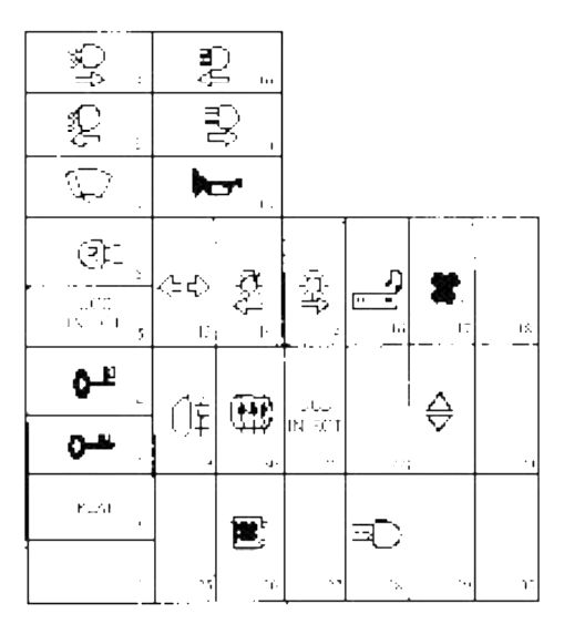
The cockpit fuse box is placed in driving post left side, being attached on the dashboard lateral side.
Dacia Solenza – fuse box diagram – passenger compartment
Fuse
[A]
Circuit protected
F02
15
Instrument panel, UCE cockpit (ceiling lamp), radio (I.C.)
F03
20
UCE cockpit, climate control panel AC (I.C.)
F04
15
U.C.E. cockpit, diagnostic socket, UCE airbag, anti-starting bushing (DC)
F05
10
U.C.E. injection, fuel pump relay/ ignition coil, instrument panel (DC)
F06
10
Windscreen washer-wiper switch (windscreen washing pump), reverse driving switch, STOP contact (I DC), air conditioning climate control panel.
F07
20
Windscreen wiper switch, UCE cockpit (wiper timer operation), windscreen wiper motor (stopping at fix point).
F08
7,5
Left meeting lights, instrument panel (indicator)
F09
7,5
Right meeting lights
F10
7,5
Left road lights, instrument panel (indicator)
F11
7,5
Right road lights
F12
15
Acoustic warning
F13
25
UCE cockpit(turning lights and hazard), diagnostic socket (IIC)
F14
7,5
Front/rear parking lights, lighting: switches, climate control panel, instrument panel, lighter, radio.
F15
7,5
Front/rear right parking lights
F16
15
Lighter, radio
F17
30
Climate control blower
F19
7,5
Fog lamp, instrument panel (indicator)
F20
25
Rear window defrosting
F21
5
U.C.E. injection
F23
30
Electric left/right window switch
F26
30
Climate control blower
F28
20
Fog projectors
The fusible F26 is used only for vehicles equipped with air conditioning
Engine compartment
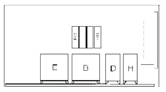
Vehicles without air conditioning
The fuse box placed in the engine compartment is attached in front of the left shock absorber column.
Dacia Solenza – fuse box diagram – engine compartment (without A/C)
Fuse
[A]
Circuit protected
F01
25
Engine cooling fan
F04
30
Injectors, oxygen sensor heating resistance, canister purging valve, injection computer, fuel pump, ignition coil., vehicle speed transducer
B
30
Engine cooling fan
D
30
Injectors, canister purging valve, oxygen sensorheating resistance, injection computer, and vehiclespeed transducer.
E*
30
Fog projectors
H
30
Fuel pump
Ignition coil
∗- for vehicles equipped with fog projectors
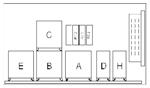
Vehicles with air conditioning
The fuse box placed in the engine compartment is attached in front of the left shock absorber column,
Dacia Solenza – fuse box diagram – engine compartment (with A/C)
Fuse
[A]
Circuit protected
F02
40
Engine cooling fan
F03
7,5
AC compressor
F04
30
Injectors, oxygen sensor heating resistance, canister purging valve, injection computer, fuel pump, ignition coil, vehicle speed transducer
A
30
AC compressor
B
30
Engine cooling fan – 1/st speed
C
40
Engine cooling fan – 2/nd speed
D
30
Injectors, canister purging valve, oxygen sensor heating resistance, injection computer, and vehicle speed transducer
E*
30
Fog projectors
H
30
Fuel pomp, ignition coil
∗- for vehicles equipped with fog projectors
WARNING: Terminal and harness assignments for individual connectors will vary depending on vehicle equipment level, model, and market.