Dodge Dakota (1997 – 2000) – fuse box diagram
Year of production: 1997, 1998, 1999, 2000
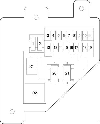
Passenger Compartment Fuse Box
 Dodge Dakota – fuse box diagram – passenger compartment
No.
|
A
|
Protected Component |
| 1 |
20 |
Headlamp Flasher Relay, Air Conditioner Compressor Clutch Relay, Horn Relay, Central Timer Module (VTSS) |
| 2 |
15 |
Park/Neutral Position Switch (Automatic Transmission), Back-Up Lamp Switch (Manual Transmission) |
| 3 |
10 |
ABS |
| 4 |
15 |
Instrument Cluster |
| 5 |
5 |
A/C Heater Control, Heater Control (except A/C), Ash Receiver Lamp, Radio, Instrument Cluster |
| 6 |
20 |
Wiper Relay, Multi-Function Switch, Central Timer Module, Wiper Motor |
| 7 |
15 |
Blower Motor Relay, Air Conditioner Compressor Clutch Relay |
| 8 |
10 |
Radio |
| 9 |
10 |
Diesel: Engine Control Module, Fuel Heater Relay |
| 10 |
Gasoline: Powertrain Control Module, Fuel Pump Relay, Automatic Shut Down Relay, Radiator Fan Relay |
| 10 |
15 |
Combination Flasher |
| 11 |
10 |
EVAP/Purge Solenoid, Overhead Console, Central Timer Module |
| 12 |
15 |
Glove Box Lamp, Radio, Data Link Connector, Underhood Lamp/Switch, Dome Lamp, Overhead Console, Power Mirror Switch |
| 13 |
20 |
Central Timer Switch, Power Window/Door Lock Switch |
| 14 |
15 |
Headlamp Switch (City Lamp, Tail/Stop Lamp, License Lamp, A/C Heater Control, Heater Control (except A/C), Ash Receiver Lamp, Radio, Instrument Cluster) |
| 15 |
15 |
Cigar Lighter |
| 16 |
– |
– |
| 17 |
10 |
Instrument Cluster |
| 18 |
10 |
Airbag Control Module |
| 19 |
10 |
Airbag Control Module, Passenger Airbag On/Off Switch |
| Circuit Breaker |
| 20 |
25 |
Power Window/Door Lock Switch |
| 21 |
– |
– |
Relay
|
| R1 |
Horn |
| R2 |
Combination Flasher |
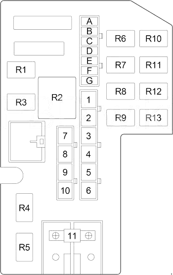
Engine Compartment Fuse Box
 Dodge Dakota – fuse box diagram – engine compartment
No.
|
A
|
Protected Component |
| A |
25 |
Diesel: Air Conditioner Compressor Clutch Relay, Engine ControlModule, Powertrain Control Module, Electric Vacuum Modulator |
| 15 |
Gasoline: Oxygen Sensor |
| B |
15 |
Left Headlamp |
| C |
20 |
Fog Lamp Relay |
| D |
25 |
Combination Flasher |
| E |
20 |
Stop Lamp Switch |
| F |
10 |
Diesel: Automatic Shut Down Relay, Powertrain Control Module |
| 20 |
Gasoline: Transmission Control Relay |
| G |
15 |
Right Headlamp |
| 1 |
50 |
Diesel: Fuel Heater Relay |
| 20 |
Gasoline: Powertrain Control Module, Fuel Pump Relay |
| 2 |
20 |
Diesel: Power Outlet |
| 30 |
Gasoline: Radiator Fan Relay |
| 3 |
50 |
Diesel: Automatic Shut Down Relay (Fuel Injection Pump, Glow Plug Relay, Fuse: “A”) |
| 30 |
Gasoline: Automatic Shut Down Relay (Fuel Injector, Ignition Coil, Powertrain Control Module, Fuse: “A”) |
| 4 |
50 |
Diesel: Glow Plug Relay |
| 20 |
Gasoline: Power Outlet |
| 5 |
40 |
Blower Motor Relay |
| 6 |
50 |
Diesel: Glow Plug Relay |
| 7 |
50 |
Fuse (Passenger Compartment): “1”, “4”, “12”, “13”, “14”, “21” |
| 8 |
30 |
ABS |
| 9 |
40 |
Starter Relay, Ignition Switch (Fuse (Passenger Compartment): “2”,”3″, “7”, “18”, “20”), Radiator Fan Relay, Fuel Pump Relay, Automatic Shut Down Relay |
| 10 |
40 |
Ignition Switch (Starter Relay, Fuse (Passenger Compartment): “6”, “8”, “9”, “10”, “11”, “15”, “16”, “17”, “19”) |
| 11 |
140 |
Generator |
Relay
|
| R1 |
Wiper |
| R2 |
Blower Motor |
| R3 |
Starter |
| R4 |
– |
| R5 |
Fog Lamp |
| R6 |
– |
| R7 |
Gasoline: Transmission Control |
| R8 |
Air Conditioner Compressor Clutch |
| R9 |
Automatic Shut Down |
| R10 |
– |
| R11 |
Gasoline: Radiator Fan |
| R12 |
Headlamp Flasher |
| R13 |
Gasoline: Fuel Pump |
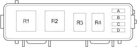
Engine Compartment Relay Box
 Dodge Dakota – fuse box diagram – engine relay box
No.
|
A
|
Protected Component |
| 1 |
– |
– |
| 2 |
– |
– |
| 3 |
– |
– |
| 4 |
– |
– |
Relay
|
| R1 |
– |
| R2 |
Fuel Heater Relay |
| R3 |
– |
| R4 |
– |
WARNING: Terminal and harness assignments for individual connectors will vary depending on vehicle equipment level, model, and market.