Dodge Durango (2004 – 2009) – fuse box diagram
Year of production: 2004, 2005, 2006, 2007, 2008, 2009
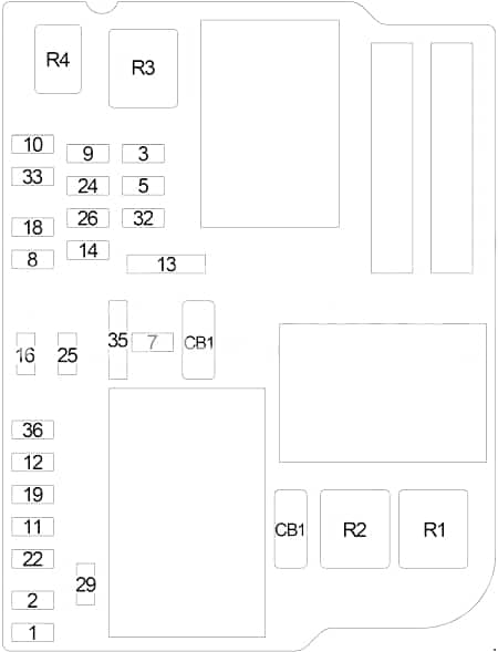
Passenger Compartment Fuse Box
 Dodge Durango – fuse box diagram – passenger compartment
| No. |
A
|
Circuit Protected
|
| 1 |
– |
– |
| 2 |
10 |
Power Mirror |
| 3 |
20 |
Power Outlet – Instrument Panel |
| 4 |
– |
– |
| 5 |
– |
– |
| 6 |
– |
– |
| 7 |
25 |
Radio Amplifier |
| 8 |
10 |
Mirror Switch, Mirror Memory Module |
| 9 |
20 |
Cluster |
| 10 |
15 |
Cluster |
| 11 |
10 |
Satellite Receiver, Monitor/DVD Media System |
| 12 |
25 |
Radio |
| 13 |
15 |
A/C Heater Control (Automatic A/C) |
| 14 |
15 |
Electronic Overhead Module, Data Link Connector, Hands-Free Module, Sentry Key Remote Entry Module, Air Conditioner Compressor Clutch Relay, Fuel Pump Relay, Powertrain Control Module |
| 15 |
– |
– |
| 16 |
10 |
Occupant Classification Module, Occupant Restraint Controller Module, Passenger Airbag On/Off Indicator Lamp |
| 17 |
– |
– |
| 18 |
10 |
Sentry Key Remote Entry Module, Integrate Power Module, Air Conditioner Compressor Clutch Relay, Fuel Pump Relay, Powertrain Control Module |
| 19 |
10 |
Cluster, Transfer Case Selector Switch, Driver/Passenger Heated Seat Switch, Inside Rearview Mirror, Infrared Sensor |
| 20 |
– |
– |
| 21 |
– |
– |
| 22 |
– |
– |
| 23 |
– |
– |
| 24 |
10 |
A/C Heater Control (Manual A/C), Rear A /C Heater Control (Automatic A/C), Rear Blower Motor Relay, Rear Window Defogger Relay |
| 25 |
10 |
Occupant Restraint Controller Module |
| 26 |
10 |
ABS, Stop Lamp Inhibit (Traction Control), Steering Angle Sensor (Traction Control), Dynamics Sensor (Traction Control) |
| 27 |
– |
– |
| 28 |
– |
– |
| 29 |
– |
– |
| 30 |
– |
– |
| 31 |
– |
– |
| 32 |
10 |
’03-’04: Starter Relay, Powertrain ControlModule, Cluster |
| 33 |
10 |
Occupant Classification Module |
| 36 |
10 |
Powertrain Control Module, Cluster |
| 35 |
20 |
Power Outlet – Console, Rear Power Outlet |
| Circuit Breaker |
| CB1 |
25 |
Sunroof Motor, Power Window |
| CB2 |
– |
– |
Relay
|
| R1 |
Rear Window Defogger |
| R2 |
Rear Blower Motor |
| R3 |
Accessory |
| R4 |
– |
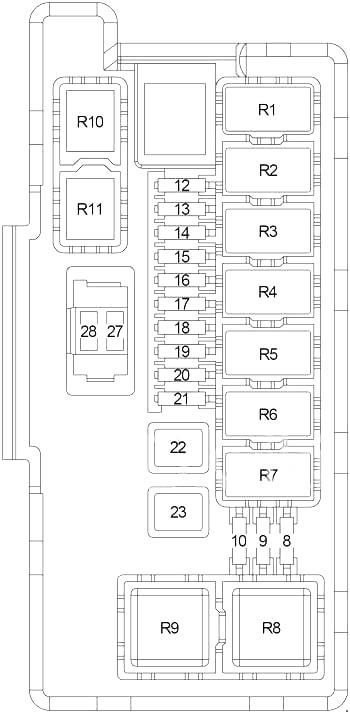
Integrated Power Module
 Dodge Durango – fuse box diagram – integrated power module
| No. |
A
|
Circuit Protected
|
| 8 |
10 |
Left Front Park/Turn Lamp, Left Front Marker Side Lamp, Left Tail/Stop/Turn Lamp, License Lamp |
| 9 |
10 |
Trailer Tow Connector |
| 10 |
10 |
Right Front Park/Turn Lamp, Right Front Marker Side Lamp, Right Tail/Stop/Turn Lamp |
| 12 |
20 |
Front Control Module |
| 13 |
20 |
Front Control Module |
| 14 |
20 |
Adjustable Pedals Relay |
| 15 |
20 |
Fog Lamp Relay |
| 16 |
20 |
Horn Relay |
| 17 |
20 |
Wiper Rear Relay |
| 18 |
20 |
Front Control Module |
| 19 |
20 |
’05-’09: Left Trailer Tow Relay (Trailer Tow Brake Lamp Relay Control, Trailer Connector) |
| 15 |
’03-’04: Left Trailer Tow Relay (Trailer Tow Brake Lamp Relay Control, Trailer Connector) |
| 20 |
20 |
Front Control Module |
| 21 |
20 |
’05-’09: Right Trailer Tow Relay (Trailer Tow Brake Lamp Relay Control, Trailer Connector) |
| 15 |
’03-’04: Right Trailer Tow Relay (Trailer Tow Brake Lamp Relay Control, Trailer Connector) |
| 22 |
30 |
Front Control Module |
| 23 |
40 |
Radiator Fan (High) Relay, Radiator Fan (Low) Relay |
| 27 |
30 |
Front Control Module, Fuse (Passenger Compartment): “11”, “12” |
| 28 |
30 |
Fuse (Passenger Compartment): “13”, “14” |
Relay
|
| R1 |
Wiper On/Off |
| R2 |
Wiper High/Low |
| R3 |
Horn |
| R4 |
Wiper Rear |
| R5 |
Left Trailer Tow |
| R6 |
Right Trailer Tow |
| R7 |
Park Lamp |
| R8 |
Radiator Fan (High) |
| R9 |
Radiator Fan (Low) |
| R10 |
Fog Lamp |
| R11 |
Adjustable Pedals |
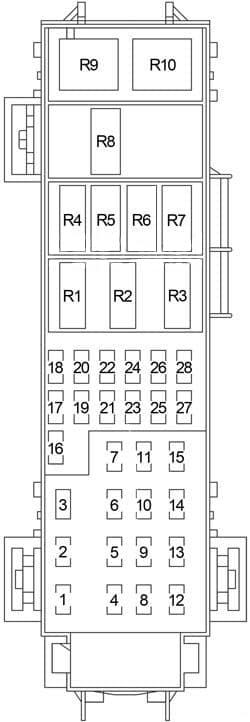
Engine Compartment Fuse Box
 Dodge Durango – fuse box diagram – engine compartment
| No. |
A
|
Circuit Protected
|
| 1 |
30 |
Starter Relay, Ignition Switch (Fuse (Passenger Compartment): “16”, “18”, “19”, “32”, “34”; (Engine Compartment): “16”), Run/Start Relay |
| 2 |
30 |
Integrate Power Module (Wiper High/Low Relay, Wiper On/Off Relay) |
| 3 |
40 |
Brake Provision Module |
| 4 |
30 |
Ignition Switch (Fuse (Passenger Compartment): “25”), Sunroof Motor, Fuse (Passenger Compartment): “35” |
| 5 |
40 |
’05-’09: Driver/Passenger Seat Switch, Heated Seat Module, Seat Memory Module |
| 50 |
’03-’04: Driver/Passenger Seat Switch, Heated Seat Module, Seat Memory Module |
| 6 |
20 |
Ignition Switch (Fuse (Passenger Compartment): “24”, “25”, “26”) |
| 7 |
40 |
Front Blower Motor Relay, Run/Remote Relay |
| 8 |
40 |
Accessory Relay (Circuit Breaker, Fuse (Passenger Compartment): “3”) |
| 9 |
– |
– |
| 10 |
30 |
Automatic Shut Down Relay (Powertrain Control Module, ASD Relay, Ignition Coil, Fuel Injector, Ignition Capacitor) |
| 11 |
40 |
’05-’09: Liftgate Power Module |
| 12 |
40 |
Rear Window Defogger Relay (Fuse (Passenger Compartment): “2”), Shift Motor/Mode Sensor Assembly |
| 13 |
30 |
Rear Blower Motor Relay |
| 14 |
40 |
ABS |
| 15 |
50 |
Fuse (Passenger Compartment): “7”, “8”, “9”, “10”, “33” |
| 16 |
10 |
’05-’09: Starter Relay, Cluster, Powertrain Control Module, Front Control Module |
| 17 |
– |
– |
| 18 |
20 |
Fuel Pump Relay |
| 19 |
20 |
Transmission Control Relay |
| 20 |
– |
– |
| 21 |
20 |
ABS |
| 22 |
20 |
Powertrain Control Module |
| 23 |
20 |
Trailer Tow Connector |
| 24 |
15 |
Air Conditioner Compressor Clutch Relay |
| 25 |
15 |
Stop Lamp Switch |
| 26 |
– |
– |
| 27 |
10 |
Ignition Switch (Instrument Cluster) |
| 28 |
– |
– |
Relay
|
| R1 |
’05-’09: Run/Start |
| R2 |
’05-’09: Run/Remote |
| R3 |
– |
| R4 |
Starter |
| R5 |
Transmission Control |
| R6 |
Air Conditioner Compressor Clutch |
| R7 |
Fuel Pump |
| R8 |
’05-’09: Stop Lamp Inhibit (Traction Control) |
| R9 |
Front Blower Motor |
| R10 |
Automatic Shut Down |
WARNING: Terminal and harness assignments for individual connectors will vary depending on vehicle equipment level, model, and market.