Eagle Talon (1996) – fuse box diagram
Year of production: 1996
Fuse box diagram
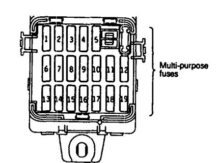
| Power supply circuit | No. | A | Load circuit | |
| Battery | 1 | 15 | Amplifier | |
| Ignition switch | IG2 | 2 | — | — |
| IG1 | 3 | 10 | Back-up light, combination meter <non-turbo>, EATX-ECM <non-turbo (A/T) and SRS-ECU | |
| 4 | 10 | Turn signal and hazard flasher unit | ||
| Battery | 5 | 10 | Theft-alarm horn and theft-alarm horn relay | |
| 6 | 30 | Defogger and defogger switch | ||
| Ignition switch | IG2 | 7 | — | — |
| IG1 | 8 | 10 | Auto-cruise main switch, auto-cruise control vacuum pump <turbo>, auto-cruise-ECU, auto-cruise speed control assembly <non-turbo>, combination meter, ETACS-ECU, powertrain control module <non-turbo>, SRS-ECU and sunroof-ECU | |
| ACC | 9 | 20 | ETACS-ECU, intermittent wiper relay, wiper and washer motor | |
| Battery | 10 | 10 | Door lock actuator and door lock power relay | |
| 11 | 30 | Blower motor | ||
| Ignition switch | ACC | 12 | — | — |
| IG2 | 13 | 10 | ABS-ECU <FWD>, ABS power relay <AWD>, A/C switch, automatic compressor-ECM, blower motor relay, defogger relay and DRL-ECU <CANADA> | |
| ACC | 14 | 15 | Cigarette lighter | |
| IG2 | 15 | 10 | Auto-cruse-ECU <turbo>, combination meter <turbo> and ELC 4-speed automatic transaxle control module <turbo> | |
| Battery | 16 | — | — | |
| 17 | 20 | Sunroof-ECU | ||
WARNING: Terminal and harness assignments for individual connectors will vary depending on vehicle equipment level, model, and market.