Eagle Talon (1997 – 1998) – fuse box diagram
Year of production: 1997, 1998
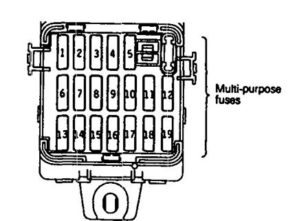
Fuse box diagram
Eagle Talon – fuse box diagram
Power supply circuit
No.
A
Load circuit
Battery
1
15
Amplifier
Ignition switch
IG2
2
—
—
IG1
3
10
Back-up light, combination meter <non-turbo>, EATX-ECM <non-turbo (A/T) and SRS-ECU
4
10
Turn signal and hazard flasher unit
Battery
5
10
Theft-alarm horn and theft-alarm horn relay
6
30
Defogger and defogger switch
Ignition switch
IG2
7
—
—
IG1
8
10
Auto-cruise main switch, auto-cruise control vacuum pump <turbo>, auto-cruise-ECU, auto-cruise speed control assembly <non-turbo>, combination meter, ETACS-ECU, powertrain control module <non-turbo>, SRS-ECU and sunroof-ECU
ACC
9
20
ETACS-ECU, intermittent wiper relay, wiper and washer motor
Battery
10
10
Door lock actuator and door lock power relay
11
30
Blower motor
Ignition switch
ACC
12
—
—
IG2
13
10
ABS-ECU <FWD>, ABS power relay <AWD>, A/C switch, automatic compressor-ECM, blower motor relay, defogger relay and DRL-ECU <CANADA>
ACC
14
15
Cigarette lighter
IG2
15
10
Auto-cruse-ECU <turbo>, combination meter <turbo> and ELC 4-speed automatic transaxle control module <turbo>
Battery
16
—
—
17
20
Sunroof-ECU
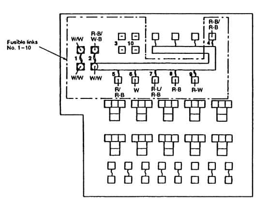
Eagle Talon – fuse box diagram
No.
Circuit
Housing color
A
1
Generator
Wine red
120
2
Dedicated fuses No. 8, 11 and multi-purpose fuses No. 1, 5 , 6, 10, 11
Yellow
60
3
—
—
—
4
MFI system and ELC 4-speed automatic transaxle
Pink
30
5
Headlight, fog light and taillight
Green
40
6
Multi-prupose fuse No. 17 and ignition switch
Pink
30
7
Radiator fan
Pink
30
8
ABS system
Red
50
9
Power windows
Pink
30
10
—
—
—
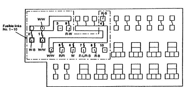
Eagle Talon – fuse box diagram
No.
Circuit
Housing color
A
1
Fusible links No. 2, 9 and generator
Blue
120
2
Dedicated fuses No. 8, 11 and multi-purpose fuses No. 1, 5 , 6, 10, 11
Yellow
60
3
—
—
—
4
MFI system
Blue
20
5
Headlight, fog light and taillight
Green
40
6
Multi-prupose fuse No. 17 and ignition switch
Pink
30
7
Radiator fan
Pink
30
8
ABS system
Red
50
9
Power seat and power windows
Pink
30
10
—
—
—
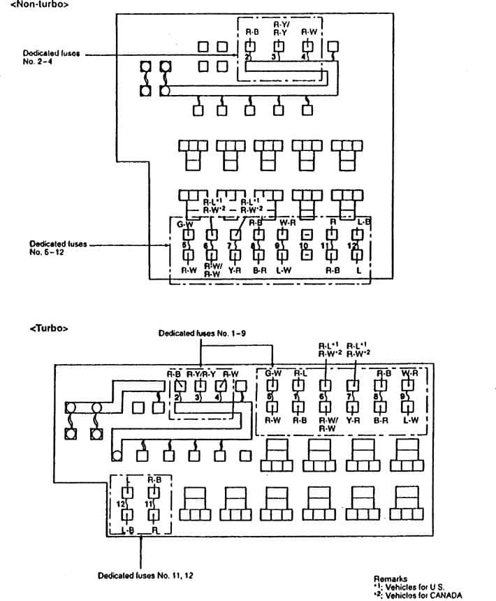
Eagle Talon – fuse box diagram
Power supply circuit
No.
A
Housing color
Circuit
Fusible link No. 8
1
10
Red
ABS system <AWD>
Battery
2
20*1
Yellow
ABS system, auto-cruise control system and stop light
15*2
Blue
3
15
Blue
Horn
4
15
Blue
Turn signal light and hazard light
Taillight relay
5
15
Blue
Glove compartment light, license plate light, lighting monitor buzzer, rheostat, side marker light, taillight and illumination light
Headlight relay
6
15
Blue
Fog light
7
10
Red
High-beam indicator light
Fusible link No.2
8
10
Red
A/C compressor
Battery
9
20
Yellow
Condenser fan
—
10
—
—
—
Fusible link No. 2
11
10
Red
Auto-cruise-ECU (battery back up) >turbo>, dome light, door-ajar warning light ELC 4-speed automatic transaxle control module (battery back up) <turbo>, engine control module (battery back up) <turbo>, ETACS-ECU, foot light, Ignition key hole illumination light luggage compartment light, radio, receiver, scan tool power source, theft-alarm system, universal garage door opener and vanity mirror light
Ignition switch (ACC)
12
10
Red
Auto-cruise control system <turbo>, radio and receiver
*1: NON-TURBO
*2: TURBO
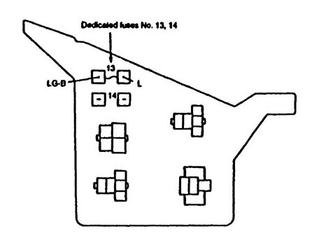
Eagle Talon – fuse box diagram
Power supply circuit
No.
A
Housing color
Cicuit
Ignition switch (ACC)
13
10
Red
Remote controlled mirror
Defogger relay
14
—
—
—
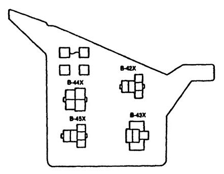
Eagle Talon – fuse box diagram
Connector No.
Name
B-42X
Power window relay
B-43X
Theft-alarm starter relay <M/T>
B-44X
Theft-alarm starter relay <A/T>
B-45X
Theft alarm horn relay
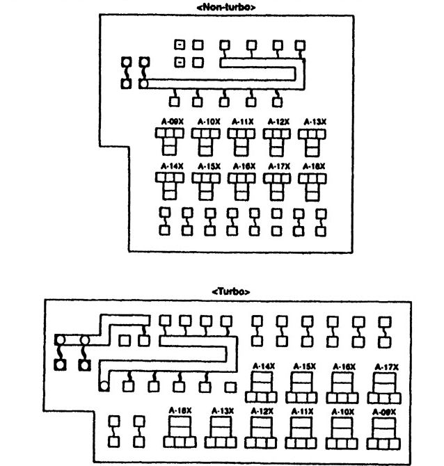
Relays
Eagle Talon – fuse box diagram – relays
Connector No.
Name
A-09X
Condenser fan relay (LO)
A-10X
Condenser fan relay (HI)
A-11X
Radiator fan relay (LO1)
A-12X
Radiator fan relay (LO2) <Turbo>
A-13X
Radiator fan relay (HI)
A-14X
Headlight relay
A-15X
Tailight relay
A-16X
Fog light relay
A-17X
Horn relay
A-18X
A/C compressor clutch relay
WARNING: Terminal and harness assignments for individual connectors will vary depending on vehicle equipment level, model, and market.