Eagle Vision (1997) – fuse box diagram
Year of production: 1997
Engine compartment
Power distribution center
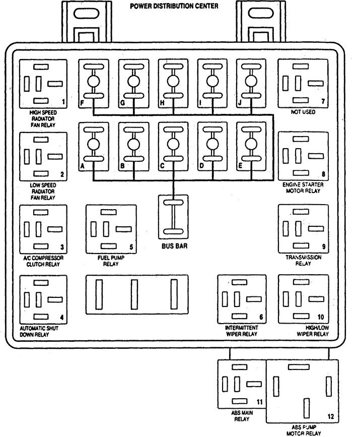
| Fuse | A | Function |
| A | 20 | Splice 107 |
| B | 20 | Splice 116 |
| C | 40 | ABS |
| D | 40 | Splice 102 |
| E | 30 | Wiper |
| F | 20 | Junction Block |
| G | 20 | Junction Block |
| H | 30 | DRL, Splice 111 & Junction Block |
| I | 30 | Splice 104 |
| J | 40 | Ignition Switch |
Junction block
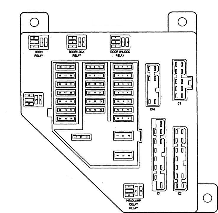
| Fuse | A | Function |
| 1 | 5 | Power Mirrors |
| 2 | 10 | Radio |
| 3 | 10 | Flasher |
| 4 | 20 | Sloplamp Switch |
| 5 | 5 | BCM |
| 6 | 10 | A/C & Splice 111 |
| 7 | 10 | Air Bag |
| 8 | 20 | Cigar Lighter & Radio |
| 9 | 15 | Splice 206 |
| 10 | 10 | Wiper |
| 11 | 15 | LH Headlamp |
| 12 | 15 | Splice 115 |
| 13 | 10 | Splices 207, 2223, 301, 317 & 322, Trunk Lamp, Underhood Lamp |
| 14 | 5 | Splices 220, 239, 314 & 319 |
| 15 | 15 | LH Headlamp |
| 16 | 15 | Headlamp Switch & Splice 126 |
| 17 | 5 | Splice 213 & TCM |
| 18 | 10 | Splice 120 |
| 19 | 10 | Air Bag |
| 20 | 10 | Splice 124 |
| 21 | 25 | ATC Power Module & Blower Motor Resistor |
| 22 | CB20 | Power Windows |
| 23 | CB20 | Power Antenna, Power Seats & Sunroof Control Module |
| 24 | — | — |
WARNING: Terminal and harness assignments for individual connectors will vary depending on vehicle equipment level, model, and market.