Ferrari 599 (2006 – 2012) – fuse box diagram
Year of production: 2006, 2007, 2008, 2009, 2010, 2011, 2012
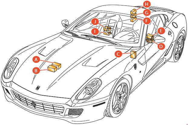
Location
Ferrari 599 GTB Fiorano
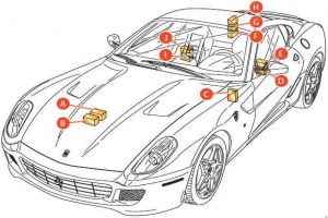 Ferrari 599 – fuse box diagram – location GTM Fiorano
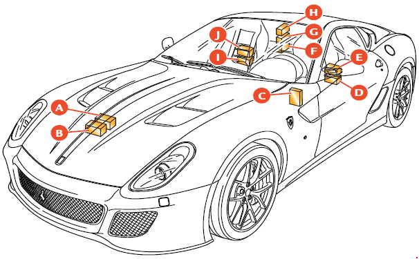
Ferrari 599 GTO
 Ferrari 599 – fuse box diagram – location GTO
| Number |
Location |
| A |
Fuses and realys in the engine compartment |
| B |
Fuses and realys in the engine compartment |
| C |
Body computer fuses and relays |
| D |
Fuses and relays in the passenger compartment, driver side |
| E |
Fuses and relays in the passenger compartment, driver side |
| F |
Fuses and relays in the luggage compartment |
| G |
Fuses and relays in the luggage compartment |
| H |
Fuses and relays in the luggage compartment |
| I |
Fuses and relays in the passenger compartment, passenger side |
| J |
Fuses and relays in the passenger compartment, passenger side |
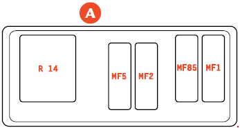
Fuses and relays in the engine compartment
A
 Ferrari 599 – fuse box diagram – engine compartment – box A
| Number |
Fuse rating [A] |
Description |
| MF5 |
40 |
+30 A.C. unit |
| MF2 |
60 |
+30 Air pump (Link Box) |
| MF85 |
40 |
Passenger compartment connected devices 2 |
| MF1 |
40 |
+30 ABS (pump) (Link Box) |
| Relay |
| R14 |
50 |
Air pump |
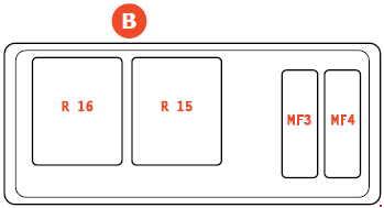
B
 Ferrari 599 – fuse box diagram – engine compartment – box B
| Number |
Fuse rating [A] |
Description |
| MF3 |
40 |
+30 RH fans (Link Box) |
| MF4 |
40 |
+30 LH fans (Link Box) |
| Relay |
| R16 |
50 |
LH fans |
| R15 |
50 |
RH fans |
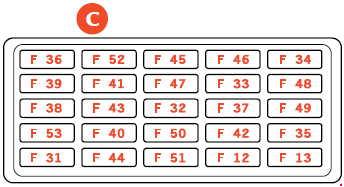
Body Computer fuses and relays
C
 Ferrari 599 – fuse box diagram – body computer
– box C
| Number |
Fuse rating [A] |
Protected component |
| F36 |
10 |
+30 Glove compartment motor |
| F52 |
15 |
Driver seat heating (INT/A connected device relay) |
| F45 |
25 |
— |
| F46 |
15 |
— |
| F34 |
20 |
— |
| F39 |
10 |
+30 for NIM, NCL, diagnostic socket OBD, CSA, CAV, radio/NTT, telephone option |
| F41 |
15 |
— |
| F47 |
20 |
— |
| F33 |
20 |
— |
| F48 |
20 |
— |
| F38 |
15 |
+30 Ratio motor for luggage compartment lock |
| F43 |
30 |
Windshield wipers/washer (INT/A connected device relay) |
| F32 |
10 |
+30 Dome lights |
| F37 |
10 |
+15 NQS, +15 CLA (NO), third stop |
| F49 |
7,5 |
+15 for CSG, CSP, NIM, NCL, radio/NIT, CEM, CRP, telephone option, dome light panel, windshield wiper controls, steering column adjustment |
| F53 |
10 |
+30 Rear fog light |
| F40 |
30 |
+30 Heated rear window (INT/A relay) |
| F50 |
7,5 |
+ 15 Airbag system |
| F42 |
7,5 |
+ 15 NFR |
| F35 |
7,5 |
+ 15 CLA (NC), IFR, engine signal socket, relay coils (headlight washer, reverse gear, high beams) |
| F31 |
7,5 |
INT/A for A.C. unit, NBC |
| F44 |
20 |
+30 Cigarette lighter, passenger seat heating (INT/A connected device relay) |
| F51 |
7,5 |
+15 NCR, FI control panel |
| F12 |
15 |
+30 RH low beam |
| F13 |
15 |
+30 LH low beam |
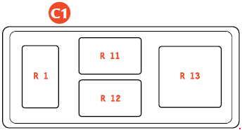
C1
Ferrari 599 – fuse box diagram – body computer
– box C1
| Number |
Ampere ratting [A] |
Description |
| R01 |
20 |
Low beams |
| R11 |
30 |
Heated rear window |
| R12 |
30 |
Connected devices 1 (controlled by INT/A ignition switch) |
| R13 |
50 |
Connected devices 2 (NBC-controlled) (option) |
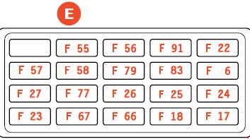
Fuses and relays in the passenger compartment (driver-side)
E
 Ferrari 599 – fuse box diagram – passenger compartment – box E
| Number |
Ampere ratting [A] |
Description |
| F55 |
20 |
+30 Steering column adjustment (only with basic seat version) |
| F56 |
30 |
+30 Passenger seat adjustment |
| F91 |
7,5 |
+30 NAP (electronics) |
| F22 |
20 |
LH main injection relay |
| F57 |
7,5 |
+ 15 Alternator, NVO, start button |
| F58 |
5 |
+30 NTP |
| F79 |
5 |
+30 NQS |
| F83 |
30 |
+30 NPG power supply |
| F6 |
25 |
+30 From ignition switch |
| F27 |
10 |
+ 15 LH injection |
| F77 |
15 |
+87 LH oxygen sensor main relay |
| F26 |
15 |
+87 Injectors main relay, LH coils |
| F25 |
10 |
Solenoid valves, air flow meter, LH diagnostic pump |
| F24 |
10 |
+87 LH main relay |
| F23 |
7,5 |
+30 LH injection |
| F67 |
5 |
+30 Front RH – rear LH side marker |
| F66 |
5 |
+30 Front LH – rear RH side marker |
| F18 |
10 |
+30 RH high beam |
| F17 |
10 |
+30 LH high beam |
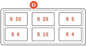
D
 Ferrari 599 – fuse box diagram – passenger compartment – box D
| Number |
Ampere ratting [A] |
Description |
| R4 |
20 |
GTB Fiorano: Horns
GTO: A.C. compressor |
| R10 |
20 |
Left-hand injection |
| R6 |
20 |
High beams |
| R5 |
30 |
Headlight washers |
| R29 |
20 |
Glove compartment motor |
| R20 |
20 |
Side marker |
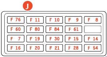
Fuses and relays in the passenger compartment (passenger-side)
J
Ferrari 599 – fuse box diagram – passenger compartment – box J
| Number |
Ampere ratting [A] |
Description |
| F76 |
15 |
+87 RH oxygen sensor main relay |
| F11 |
15 |
+87 RH injectors main relay, coils |
| F10 |
10 |
+87 Main relay, air flow meter, RH solenoid valves |
| F9 |
10 |
+F887 RH main relay (pin F03) |
| F8 |
7,5 |
+30 RH injection (pin F62) |
| F60 |
20 |
+30 NPG, NPP door lock actuator |
| F80 |
25 |
+30 Hi-Fi system (bass-box and subwoofer) |
| F84 |
30 |
+30 NPP power supply |
| F61 |
7,5 |
+30 NAG (electronics) |
| F7 |
30 |
+30 Injection main relay, RH main coil relay |
| F19 |
30 |
+30 Starter motor |
| F30 |
30 |
+30 Driver seat adjustment (and steering column adjustment, only with comfort seats) |
| F15 |
5 |
+ 15 Weight sensor ECU (only for the USA) |
| F14 |
10 |
+ 15 RH injection (coils, fuel pumps relays) |
| F16 |
7,5 |
+30 A.C. compressor |
| F20 |
25 |
+30 Headlight washer |
| F21 |
15 |
+30 Horns |
| F28 |
25 |
+30 ABS (solenoid valves) |
| F54 |
10 |
+30 ABS (electronics) |
| F56 |
30 |
+30 Passenger seat adjustment (right-hand drive version only) |
| F83 |
30 |
+30 NPG power supply (right-hand drive version only) |
| F91 |
7,5 |
+30 NAP (electronics) (right-hand drive version only) |
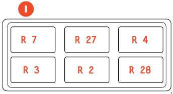
I
 Ferrari 599 – fuse box diagram – passenger compartment – box I
| Number |
Ampere ratting [A] |
Description |
| R7 |
20 |
Starter motor |
| R27 |
20 |
Devices cut-out upon ignition |
| R4 |
20 |
GTB Fiorano: A.C. compressor
GTO: Horns |
| R3 |
20 |
Immobilizer |
| R2 |
20 |
RH main injection relay |
| R28 |
20 |
Ignition cut-off with battery charger |
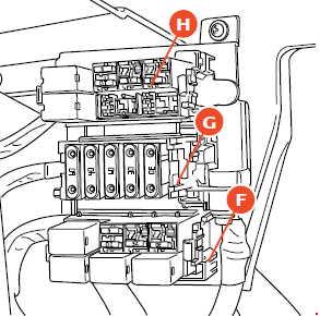
Fuses and relays in the luggage compartment
 Ferrari 599 – fuse box diagram – luggage compartment – location
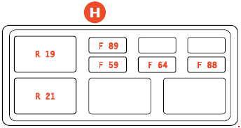
H
Ferrari 599 – fuse box diagram – luggage compartment – box H
| Number |
Ampere ratting [A] |
Description |
| F89 |
5 |
+15 NSP and NCS |
| F59 |
10 |
+30 Fuel tank door |
| F64 |
7,5 |
+30 Reverse gear, NSP |
| F88 |
30 |
+30 NCS |
| Relay |
| R19 |
20 |
Reverse gear |
| R21 |
20 |
Fuel tank door |
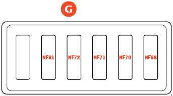
G
Ferrari 599 – fuse box diagram – luggage compartment – box G
| Number |
Ampere ratting [A] |
Description |
| MF81 |
60 |
+30 Passenger compartment connected devices 1 |
| MF72 |
40 |
+30 Luggage compartment connected devices (+side marker coil relay) |
| MF71 |
60 |
+30 Passenger compartment connected devices 3 |
| MF70 |
30 |
+30 FI gearbox pump |
| MF68 |
30 |
+30 Hi-Fi system (amplifier) |
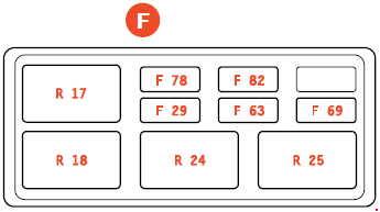
F
 Ferrari 599 – fuse box diagram – luggage compartment – box F
| Number |
Ampere ratting [A] |
Description |
| F78 |
20 |
+30 LH fuel pumps |
| F82 |
5 |
+30 Alternator sensing |
| F29 |
15 |
GTB Fiorano: +30 Battery charger
GTO: Battery conditioner |
| F63 |
20 |
+30 RH fuel pumps |
| F69 |
25 |
+30 NCR |
| Relay |
| R17 |
20 |
1st speed fuel pump, RH bank |
| R18 |
20 |
2nd speed fuel pump, RH bank |
| R24 |
20 |
1st speed fuel pump, LH bank |
| R25 |
20 |
2nd speed fuel pump, LH bank |
WARNING: Terminal and harness assignments for individual connectors will vary depending on vehicle equipment level, model, and market.