Ford Escape (2008 – 2012) – fuse box diagram
Year of production: 2008, 2009, 2010, 2011, 2012
Passenger compartment fuse panel
The fuse panel is located on the right-hand side of the center console, by the instrument panel.
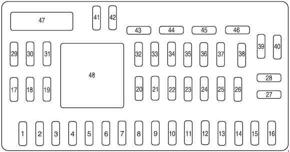
| No. | A | Protected components |
| 1 | 30 | Not used (spare) |
| 2 | 15 | Brake on/off switch |
| 3 | 15 | SYNC® module |
| 4 | 30 | Moon roof |
| 5 | 10 | Keypad illumination, Brake shift interlock (BSI), Passenger compartment fuse panel, SPDJB |
| 6 | 20 | Turn signals, Stop lamps |
| 7 | 10 | Low beam headlamps (left) |
| 8 | 10 | Low beam headlamps (right) |
| 9 | 15 | Interior lights |
| 10 | 15 | Backlighting |
| 11 | 10 | Four wheel drive |
| 12 | 7,5 | Power mirror switch |
| 13 | 7,5 | up to 2008: Canister vent |
| 14 | 10 | FCIM (radio buttons), Front display module, GPS module |
| 16 | 15 | Not used (spare) |
| 17 | 20 | All lock motor feeds, Liftgate release, Liftglass release |
| 18 | 20 | Heated seat |
| 19 | 25 | Rear wiper |
| 20 | 15 | Datalink |
| 21 | 15 | Fog lamps |
| 22 | 15 | Park lamps |
| 23 | 15 | High beam headlamps |
| 24 | 20 | Horn relay |
| 25 | 10 | Demand lamps |
| 26 | 10 | Instrument panel cluster |
| 27 | 20 | Ignition switch |
| 28 | 5 | Radio |
| 29 | 5 | Instrument panel cluster |
| 30 | 5 | Overdrive cancel |
| 31 | 10 | Restraints control module |
| 32 | 10 | Rear video camera module |
| 33 | 10 | Speed control switch |
| 34 | 5 | Speed control deactivate switch, ABS |
| 35 | 10 | Four wheel drive, EPAS (steering), Park aid module |
| 36 | 5 | Passive anti-theft system (PATS) transceiver |
| 37 | 10 | Climate Control |
| 38 | 20 | Subwoofer/Amp (Audiophile radio) |
| 39 | 20 | Radio |
| 40 | 20 | Front power point |
| 41 | 15 | Driver/passenger door lock switches, Automatic dimming mirror, Compass, Ambient lighting, Moon roof, Camera display in mirror |
| 42 | 10 | Not used (spare) |
| 43 | 10 | Rear wiper logic, Heated seats relay, Instrument cluster |
| 44 | 10 | Not used (spare) |
| 45 | 5 | Front wiper logic, Blower motor relay |
| 46 | 7,5 | OCS (restraints), PADI (restraints) |
| Circuit Breaker | ||
| 47 | 30 | Power windows, Moon roof |
| Relay | ||
| 48 | Delayed accessory relay | |
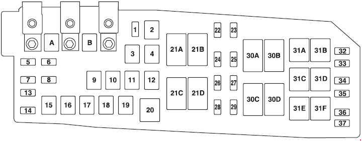
Engine Compartment Fuse Box
up to 2009
as of 2010
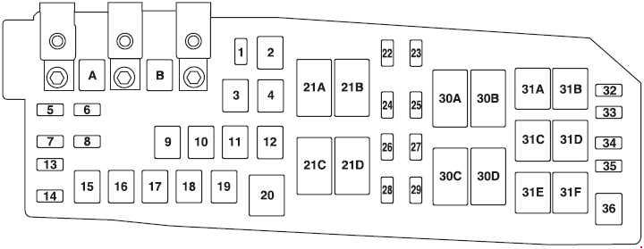
| No | A | Protected components |
| A | 80 | Electronic power steering module (EPAS) |
| B | 125 | Passenger compartment fuse panel |
| 1 | 15 | Heated mirror |
| 2 | 30 | Rear defroster |
| 3 | 20 | Rear power point (center console) |
| 4 | 20 | up to 2008: Fuel pump |
| 5 | 10 | Powertrain control module (PCM) – keep alive power, PCM relay, Canister vent (as of 2009) |
| 6 | 15 | Alternator |
| 7 | 15 | Liftgate latch |
| 8 | 20 | Trailer tow parking lamps |
| 9 | 50 | Anti-lock brake system (ABS) |
| 10 | 30 | Front wipers |
| 11 | 30 | Starter |
| 12 | 40 | Blower motor |
| 13 | 10 | A/C clutch |
| 14 | 15 | Trailer tow turn lamps |
| 15 | — | — |
| 16 | 40 | Cooling fan 1 |
| 17 | 40 | Cooling fan 2 |
| 18 | 20 | ABS solenoid |
| 19 | 30 | Power seats |
| 22 | 20 | as of 2009: Fuel pump |
| 23 | 15 | as of 2009: Fuel injectors |
| 24 | 10 | up to 2008: PCM transmission |
| 25 | 5 | as of 2009: ABS |
| 26 | 15 | as of 2009: Ignition coils |
| 10 | up to 2008: PCM mil | |
| 27 | 10 | PCM – general powertrain components malfunction indicator lamp |
| 28 | 20 | as of 2009: PCM – emission related powertrain components malfunction indicator lamp |
| 15 | up to 2008: PCM | |
| 29 | 15 | as of 2009: PCM up to 2008: Ignition coils |
| 32 | — | — |
| 35 | 10 | Run/start, Reverse lamps, Rear defrost relay |
| 36 | — | — |
| 37 | — | up to 2009: Not used |
| Relay |
||
| 20 | A/C clutch relay |
|
| 21A | Rear defroster relay | |
| 21B | as of 2009: Fuel relay | |
| 21C | Blower relay | |
| 21D | PCM relay | |
| 30A | Cooling fan 1 relay | |
| 30B | Starter relay | |
| 30C | Cooling fan main relay | |
| 30D | Cooling fan 2 relay | |
| 31A | Reverse lamp relay | |
| 31B | — | |
| 31C | Trailer tow left turn relay | |
| 31D | Trailer tow right turn relay | |
| 31E | Trailer tow park relay | |
| 31F | Liftgate latch relay | |
| Diode | ||
| 33 | PCM diode | |
| 34 | Start diode | |
WARNING: Terminal and harness assignments for individual connectors will vary depending on vehicle equipment level, model, and market.