Ford Explorer U502 (2016 – 2018) – fuse box diagram
Year of production: 2016, 2017, 2018
Passenger Compartment Fuse Panel
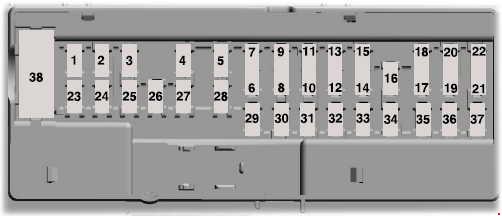
| Number | Ampers | Protected circuit |
| 1 | 10 | Demand lamps, Battery saver |
| 2 | 7,5 | Memory seat switch (lumbar power) |
| 3 | 20 | Driver unlock relay |
| 4 | 5 | Aftermarket electronic brake controller |
| 5 | 20 | Rear heated seat module |
| 6 | — | — |
| 7 | — | — |
| 8 | — | — |
| 9 | — | — |
| 10 | 5 | Securlcode™ keyless entry keypad, Hands free llftgate |
| 11 | 5 | Rear climate control module |
| 12 | 7,5 | Front climate control module |
| 13 | 7,5 | Instrument cluster, Smart data link, Steering column control module |
| 14 | 10 | 2017: Extended power module |
| 15 | 10 | Smart datallnk connector power, Heads up display |
| 16 | — | — |
| 17 | 5 | Electronic finish panel |
| 18 | 5 | Push button start switch, Ignition switch, Key Inhibit |
| 19 | 7,5 | Transmission control switch |
| 20 | — | — |
| 21 | 5 | Terrain management switch, Heads up display, Humidity sensor |
| 22 | 5 | Occupant classification sensor |
| 23 | 10 | Delayed accessory power, Power windows, Moonroof, Folding mirror relay, DC Inverter, Wlndow/moonroof switch Illumination |
| 24 | 20 | Central lock relay |
| 25 | 30 | Left-hand front smart window motor, Door zone module |
| 26 | 30 | Right-hand front smart window motor, Door zone module |
| 27 | 30 | Moonroof |
| 28 | 20 | Sony amplifier -10 channel |
| 29 | 30 | Sony amplifier -14 channel |
| 30 | — | — |
| 31 | — | — |
| 32 | 10 | SYNC, GPS module, Display, Radio frequency receiver |
| 32 | 20 | Radio |
| 34 | 30 | Run/start relay |
| 35 | 5 | Restraints control module, Extended power module (2017) |
| 36 | 15 | Lane departure warning module, Auto high beam, EC mirrors, Rear heated seats |
| 37 | 20 | Heated steering wheel |
| 38 | 30 | Left-hand front window motor, Rear power window motors |
Power Distribution Box
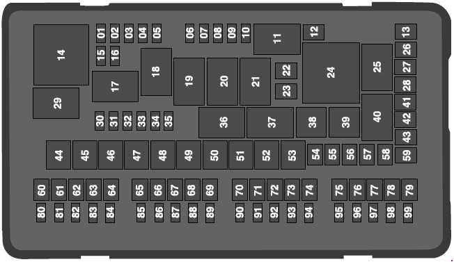
| Number | Ampers | Protected circuit |
| 1 | 20 | Powertrain control module power |
| 2 | 20 | Engine emissions (MIL) |
| 3 | 20 | A/C clutch control relay coll, VACC, Active grille shutters |
| 4 | 20 | Ignition colls |
| 5 | — | — |
| 6 | — | — |
| 7 | — | — |
| 8 | — | — |
| 9 | — | — |
| 10 | 15 | Heated mirrors |
| 12 | 40 | Heated rear window |
| 13 | — | — |
| 15 | 20 | Horn relay power |
| 16 | 10 | A/C clutch relay power |
| 22 | 25 | Electronic fan relay 2 |
| 23 | — | — |
| 24 | — | — |
| 25 | — | — |
| 26 | 30 | Anti-lock brake system valves |
| 27 | 30 | 2017: Trailer tow battery charge relay power |
| 20 | 2016: Trailer tow battery charge relay power | |
| 28 | — | — |
| 30 | — | — |
| 31 | 10 | Electric power-assisted steering |
| 32 | 10 | Anti-lock brake system module |
| 33 | 10 | Powertrain control module (ISPR) |
| 34 | 10 | Blind spot Information system, Adaptive cruise control, Front view camera, Rear camera |
| 35 | — | — |
| 41 | 40 | Rear blower motor |
| 42 | — | — |
| 43 | 40 | Front blower motor |
| 44 | 50 | Voltage quality module bus |
| 45 | 40 | Electronic fan relay 1 |
| 46 | 30 | Trailer tow brake controller |
| 47 | — | — |
| 48 | 50 | Body control module RP1 bus |
| 49 | — | — |
| 50 | 50 | Body control module RP2 bus |
| 51 | 50 | Electronic fan relay 3 |
| 52 | 60 | Anti-lock brake system pump |
| 53 | — | — |
| 54 | — | — |
| 55 | — | — |
| 56 | 40 | Power Inverter |
| 57 | — | — |
| 58 | — | — |
| 59 | — | — |
| 60 | 20 | Power point (front console bln) |
| 61 | — | — |
| 62 | 20 | Power point (Instrument panel) |
| 63 | 30 | Fuel pump |
| 64 | — | — |
| 65 | 20 | Power point (2nd row) (without USB charger) |
| 66 | — | — |
| 67 | 20 | Power point (cargo area) |
| 68 | — | — |
| 69 | 30 | Power llftgate |
| 70 | 15 | Trailer tow left-hand and rlght-har and direction Indicator lamps |
| 71 | — | — |
| 72 | 30 | Heated/cooled seats |
| 73 | 30 | Driver seat module, Driver seat power |
| 74 | 30 | Passenger seat power |
| 75 | 30 | Front wiper motor |
| 76 | — | — |
| 77 | — | — |
| 78 | 30 | 3rd row power folding seat module |
| 79 | 30 | Starter relay |
| 80 | — | — |
| 81 | 10 | Trailer tow back-up lamp relay |
| 82 | — | — |
| 83 | 10 | Brake on/off switch |
| 84 | — | — |
| 85 | 5 | 2nd row USB charger (If equipped) |
| 86 | — | — |
| 87 | — | — |
| 88 | — | — |
| 89 | — | — |
| 90 | — | — |
| 91 | — | — |
| 92 | 15 | Multi-contour seat module relay |
| 93 | 10 | Alternator sense |
| 94 | 15 | Rear washer relay |
| 95 | 15 | Rear wiper relay |
| 96 | 10 | Powertrain control module relay coll power |
| 97 | 5 | Rain sensor |
| 98 | 20 | 2nd row seat motors |
| 99 | 20 | Trailer tow parking lamp relay |
| Relay | ||
| 11 | Right hand side electronic cooling fan 3 relay | |
| 14 | Powertrain control module relay | |
| 17 | Rear heated window and heated mirrors relay | |
| 18 | Rear blower motor relay | |
| 19 | — | |
| 20 | Left hand side cooling fan relay | |
| 21 | Cooling fans series/parallel relay | |
| 29 | Run/start relay | |
| 36 | Blower motor relay | |
| 37 | Trailer tow battery charge relay | |
| 38 | A/C compressor clutch relay | |
| 39 | Horn relay | |
| 40 | — | |
WARNING: Terminal and harness assignments for individual connectors will vary depending on vehicle equipment level, model, and market.