Ford F-150 (2004 – 2008) – fuse box diagram
Year of production: 2004, 2005, 2006, 2007, 2008
Passenger compartment fuse panel / power distribution box
The fuse panel is located under the right-hand side of the instrument panel.
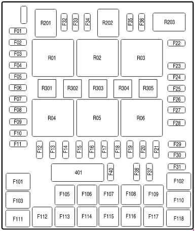
| № | A | Fuse Description |
| 1 | 10 | Run/Accessory – Wipers, Instrument cluster, Audio for XL/STX |
| 2 | 20 | Stop/Turn lamps, ABS, T/T electric brake module, PCM (BOO signal), turn signal mirrors, CHMSL |
| 3 | 7.5 | Power mirrors, Memory seats and pedals |
| 4 | 10 | DVD battery power, Power fold mirror |
| 5 | 7.5 | Keep alive memory for Powertrain Control Module (PCM) and Climate control module |
| 6 | 15 | Parklamps, Body Security Module (BSM), Instrument panel illumination |
| 7 | 5 | Radio (start signal) |
| 8 | 10 | Heated mirrors, Switch indicator |
| 9 | 20 | Fuel pump relay, Fuel injectors, Injector sense |
| 10 | 20 | Trailer tow back-up lamps relay, Trailer tow parklamp relay |
| 11 | 10 | A/C clutch, 4×4 solenoid |
| 12 | 5 | PCM relay coil |
| 13 | 10 | Climate control module power, Flasher relay |
| 14 | 10 | Back-up lamp and Daytime Running Lamps (DRL) relay coil, A/C pressure switch, Redundant speed control switch, Heated PCV (5.4L), ABS |
| 15 | 5 | Overdrive cancel, Cluster |
| 16 | 10 | Brake-shift interlock solenoid |
| 17 | 15 | Fog lamp relay |
| 18 | 10 | Electrochromatic mirror, Heated seats, BSM, Compass, RSS (Reverse Sensing System), Power rail |
| 19 | 10 | Restraints (Airbag module) |
| 20 | 10 | Power rail |
| 21 | 15 | Cluster keep alive power |
| 22 | 10 | Delayed accessory power for audio, power door lock switch and moon roof switch illumination |
| 23 | 10 | RH low beam headlamp |
| 24 | 15 | Battery saver power for demand lamps, Flex fuel |
| 25 | 10 | LH low beam headlamp |
| 26 | 20 | Horn |
| 27 | 5 | Passenger Airbag Deactivation (PAD) warning lamp, Cluster airbag warning lamp |
| 28 | 5 | SecuriLock transceiver (PATS), PCM IGN monitor |
| 29 | 15 | PCM 4×4 power |
| 30 | 15 | PCM 4×4 power |
| 31 | 20 | Radio power, Satellite radio module |
| 32 | 15 | Vapor Management Valve (VMV), A/C clutch relay, Canister vent, Heated Exhaust Gas Oxygen (HEGO) sensors #11 and #21, CMCV, Mass Air Flow (MAF) sensor, Variable Cam Timing (VCT), Heated Positive Crankcase Ventilation (PCV) valve (4.2L engine), CID sensor (4.2L engine), 4.6L/4.2L EGR |
| 33 | 15 | Shift solenoid, CMS #12 and #22, Ignition coils |
| 34 | 15 | PCM power, IMRC (4.2L) |
| 35 | 20 | Instrument cluster high beam indicator, High beam headlamps, DRL disable relay |
| 36 | 10 | Trailer tow right turn/stop lamps |
| 37 | 20 | Rear power point |
| 38 | 25 | Subwoofer power |
| 39 | – | Not used |
| 40 | 20 | Low beam headlamps, DRL |
| 41 | – | Not used |
| 42 | 10 | Trailer tow left turn/stop lamps |
| 101 | 30 | Starter solenoid |
| 102 | 20 | Ignition switch feed |
| 103 | 20 | ABS valves |
| 104 | – | Not used |
| 105 | 30 | Electric trailer brakes |
| 106 | 30 | Trailer tow battery charge |
| 107 | 30 | Power door locks (BSM) |
| 108 | 30 | Passenger power seat |
| 109 | 30 | Driver power seat, Adjustable pedals, Memory module (pedals, seats) |
| 110 | 20 | Cigar lighter, Diagnostic connector power |
| 111 | 30 | 4×4 motor relays |
| 112 | 40 | ABS pump power |
| 113 | 30 | Wipers and washer pump |
| 114 | 40 | Heated backlite, Heated mirror power |
| 115 | 20 | Moonroof |
| 116 | 30 | Blower motor |
| 117 | 20 | Instrument panel power point |
| 118 | 30 | Heated seats |
| 401 | 30 | Delayed accessory power: Power windows, Power sliding backlite |
| R01 | Full ISO relay | Starter solenoid |
| R02 | Full ISO relay | Accessory delay |
| R03 | Full ISO relay | Hi-beam headlamps |
| R04 | Full ISO relay | Heated backlite |
| R05 | Full ISO relay | Trailer tow battery charge |
| R06 | Full ISO relay | Blower motor |
| R201 | Full ISO relay | Trailer tow park lamps |
| R202 | Full ISO relay | Fog lamps |
| R203 | Full ISO relay | PCM |
| R301 | Printed circuit boar | Trailer tow backup lamps |
| R302 | – | Not used |
| R303 | Printed circuit boar | Fuel pump |
| R304 | Printed circuit boar | Battery saver |
| R305 | Printed circuit boar | Horn |
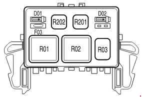
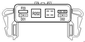
Auxiliary relay box
The relay box is located in the engine compartment on the left fender.
With Daytime Running Lamp (DRL) or 4×4 options
Without Daytime Running Lamp (DRL) and 4×4 options
| № | A |
Description |
| F03 | 5 | Clockspring illumination |
| R01 | Full ISO Relay | 4×4 CCW |
| R02 | Full ISO Relay | 4×4 CW |
| R03 | ½ ISO Relay | Daytime Running Lamps (DRL) high beam disable |
| R201 | Relay | DRL |
| R202 | Relay | A/C clutch |
| D01 | Diode | A/C clutch |
| D02 | Diode | One Touch Integrated Start (OTIS) |
WARNING: Terminal and harness assignments for individual connectors will vary depending on vehicle equipment level, model, and market.