Ford Fresstyle (2004 – 2007) – fuse box diagram
Year of production: 2004, 2005, 2006, 2007
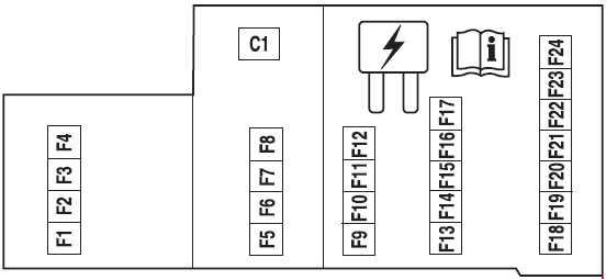
Passenger compartment fuse panel
 Ford Freestyle – fuse box diagram – passenger compartment
| Number |
A |
Description |
| F1 |
20 |
High beams |
| F2 |
15 |
Interior lamps (Courtesy and demand lamps), Delayed accessory (Power windows and moonroof) |
| F3 |
25 |
Access/Security (Power door lock actuators, Liftgate lock actuator, Liftgate solenoid) |
| F4 |
15 |
Adjustable pedal switch |
| F5 |
20 |
Horns |
| F6 |
20 |
Audio (Subwoofer) |
| F7 |
7,5 |
Power/Keep Alive Memory (KAM): Cluster and Powertrain Control Module (PCM), Climate control, Analog clock |
| F8 |
15 |
Park lamps, Side markers, Trailer tow protect |
| F9 |
20 |
Cigar lighter, Data Link Connector (DLC) |
| F10 |
7,5 |
Mirrors and memory module |
| F11 |
20 |
Audio, Family Entertainment System (FES) |
| F12 |
10 |
Back-up lamps, Electrochromatic mirror, Reverse Sensing System (RSS), Trailer tow protect |
| F13 |
7,5 |
Audio |
| F14 |
7,5 |
Starter relay coil, PCM |
| F15 |
10 |
Delayed accessory (Driver window motor logic, Auxiliary climate control switch illumination, Moonroof, Audio, Driver door lock switch illumination) |
| F16 |
10 |
Rear defroster indicator, Heated mirrors |
| F17 |
30 |
Rear defroster |
| F18 |
10 |
PCM relay coil, Shifter Brake-Shift Interlock (BS1), Passive Anti-Theft System (PATS) module, Fuel relay coil, Brake lamps, Center High-Mounted Stop Lamp (CHMSL) |
| F19 |
10 |
Anti-lock Brake System (ABS)/Traction control module, All Wheel Drive (AWD) module, RSS, Heated seat modules |
| F20 |
7,5 |
Cluster, Climate control |
| F21 |
7,5 |
Restraint Control Module (RCM) |
| F22 |
7,5 |
Auxiliary climate control relay coils, Electrochromatic mirror, Compass module |
| F23 |
7,5 |
Wiper relay coil, Blower relay coil, Cluster logic |
| F24 |
7,5 |
Occupant Classification Sensor (OCS), Passenger Air bag Deactivation (PAD) |
| Circuit breaker |
| C1 |
30 |
Delayed accessory (Front passenger window, Rear passenger windows [via window switch], Window switch illumination, Backlighting) |
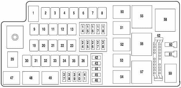
Fuse box in the engine compartment (up to 2005)
 Ford Freestyle – fuse box diagram – engine compartment
| Number |
A |
Description |
| 1 |
80 |
Interior fuse panel (SJB), SJB fuses 1, 2, 3, 4, 5, 8 and 12 |
| 2 |
— |
— |
| 3 |
— |
— |
| 4 |
50 |
Wiper RUN/ACC relay to PDB, PDB fuses 37 and 38 |
| 5 |
— |
— |
| 6 |
20 |
Moonroof |
| 7 |
— |
— |
| 8 |
60 |
Engine cooling fan |
| 9 |
— |
— |
| 10 |
40 |
Anti-lock Brake System (ABS) (Motor) |
| 11 |
30 |
Starter |
| 12 |
30 |
Powertrain Control Module (PCM) |
| 13 |
20 |
ABS (Valves) |
| 14 |
— |
— |
| 15 |
20 |
Power point (Cargo compartment) |
| 16 |
15 |
Traction Control Module (TCM) |
| 17 |
20 |
Power point (Console) |
| 18 |
10 |
Alternator |
| 19 |
40 |
Logic feed to SJB, SJB solid state devices |
| 20 |
— |
— |
| 21 |
40 |
Rear defroster |
| 22 |
30 |
Power seat motors (passenger) |
| 23 |
30 |
Heated seat modules |
| 24 |
15 |
Fog lamps |
| 25 |
10 |
A/C clutch relay, A/C compressor clutch |
| 26 |
— |
— |
| 27 |
— |
— |
| 28 |
15 |
Fuel relay (Fuel pump driver module, Fuel pump) |
| 29 |
80 |
SJB power, SJB (Circuit breaker, Fuses 6, 7, 9, 10, 11 and 15) |
| 30 |
30 |
Driver window motor |
| 31 |
— |
— |
| 32 |
30 |
Auxiliary A/C rear blower motor |
| 33 |
30 |
Driver seat motors, Memory module |
| 34 |
30 |
Ignition switch (to SJB) |
| 35 |
— |
— |
| 36 |
40 |
Front A/C blower motor |
| 37 |
30 |
Front wiper, Front washer |
| 38 |
5 |
Heated Positive Crankcase Ventilation (PCV) valve |
| 39 |
25 |
Rear wiper, Rear washer |
| 40 |
10 |
TCM, EVMV, Canister vent, ESM, Exhaust Gas Oxygen heaters, A/C clutch |
| 41 |
15 |
PCM, Injectors, Ignition coils, Mass Air Flow (MAF) sensor |
| 42 |
— |
— |
| 43 |
— |
— |
| 44 |
— |
— |
| 45 |
— |
— |
| 46 |
— |
— |
| Relay |
| 47 |
— |
| 48 |
Fog lamps |
| 49 |
— |
| 50 |
Auxiliary coolant pump |
| 51 |
A/C clutch |
| 52 |
— |
| 53 |
Fuel pump driver module, Fuel pump |
| 54 |
— |
| 55 |
PCM relay, PDB fuses 40 and 41 |
| 56 |
Starter motor solenoid |
| 57 |
Front A/C blower motor |
| 58 |
Wipers |
| 59 |
— |
| Diode |
| 60 |
PCM |
| 61 |
PCM |
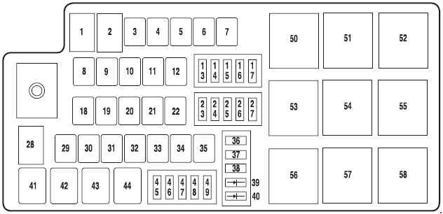
Fuse box in the engine compartment (as of 2006)
 Ford Freestyle – fuse box diagram – engine compartment
| Number |
A |
Description |
| 1 |
80 |
SJB, SJB fuses 1, 2, 3, 4, 5, 8 and 12 |
| 2 |
— |
— |
| 3 |
50 |
Front and rear wipers (fuses 45 and 47) |
| 4 |
— |
— |
| 5 |
20 |
Moonroof |
| 6 |
— |
— |
| 7 |
60 |
Engine cooling fan |
| 8 |
— |
— |
| 9 |
40 |
Anti-lock Brake System (ABS) (Motor) |
| 10 |
30 |
Starter |
| 11 |
30 |
Powertrain Control Module (PCM) relay |
| 12 |
20 |
ABS (Valves) |
| 13 |
— |
— |
| 14 |
20 |
Power point (Cargo compartment) |
| 15 |
15 |
Traction Control Module (TCM) |
| 16 |
20 |
Power point (Console) |
| 17 |
10 |
Alternator |
| 18 |
40 |
Logic feed to SJB, SJB solid state devices |
| 19 |
— |
— |
| 20 |
40 |
Rear defroster |
| 21 |
30 |
Power seat motors (passenger) |
| 22 |
30 |
Heated seat module |
| 23 |
15 |
Fog lamps |
| 24 |
10 |
A/С clutch relay, A/С compressor clutch |
| 25 |
— |
— |
| 26 |
— |
— |
| 27 |
15 |
Fuel relay (Fuel pump driver module, Fuel pump) |
| 28 |
80 |
SJB power, SJB (Circuit breaker, Fuses 6, 7, 9, 10, 11 and 15) |
| 29 |
30 |
Driver window motor |
| 30 |
— |
— |
| 31 |
30 |
Auxiliary A/C rear blower motor, Auxiliary coolant pump |
| 32 |
30 |
Driver seat motors, Memory module |
| 33 |
30 |
Ignition switch (to SJB) |
| 34 |
— |
— |
| 35 |
40 |
Front A/С blower motor |
| 36 |
10 |
Auxiliary coolant pump |
| 37 |
— |
— |
| 38 |
— |
— |
| 45 |
30 |
Front wiper, Front washer |
| 46 |
5 |
Heated Positive Crankcase Ventilation (PCV) valve |
| 47 |
25 |
Rear wiper, Rear washer |
| 48 |
10 |
TCM, EVMV, Canister vent, ESM, Exhaust Gas Oxygen heaters, A/C clutch |
| 49 |
15 |
PCM, Injectors, Ignition coils, Mass Air Flow (MAF) sensor |
| Diode |
| 39 |
PCM |
| 40 |
A/С clutch |
| Relay |
| 41 |
Fog lamps |
| 42 |
— |
| 43 |
A/С clutch |
| 44 |
Fuel pump driver module, Fuel pump |
| 50 |
PCM relay, PDB fuses 40 and 41 |
| 51 |
St art or motor solenoid |
| 52 |
Front A/C blower motor, Coolant pump relay coil |
| 53 |
— |
| 54 |
— |
| 55 |
— |
| 56 |
— |
| 57 |
Front wipers |
| 58 |
— |
WARNING: Terminal and harness assignments for individual connectors will vary depending on vehicle equipment level, model, and market.