Ford Galaxy (1995 – 2006) – fuse box diagram
Year of production: 1995, 1996, 1997, 1998, 1999, 2000, 2001, 2002, 2003, 2004, 2005, 2006
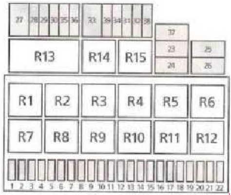
Type 1
Passenger Compartment Fuse Box
| Fuse | Ampere Rating [A] | Description |
| 1 | 10 | Dipped beam left-hand side, headlight levelling left-hand side, instrument cluster |
| 2 | 10 | Dipped beam right-hand side, headlight levelling right-hand side, instrument cluster |
| 3 | 3 | Number plate light, parking lights |
| 4 | 20 | Rear screen wiper, 2nd heat exchanger |
| 5 | 10 | Wiper motor, heated washer jets |
| 6 | 20 | Heater blower, air conditioning |
| 7 | 5 | Tail light right-hand side, chime, right side marker light |
| 8 | 5 | Tail light left-hand side, chime, left side marker light |
| 9 | 20 | Heated rear screen |
| 10 | 15 | Exterior lighting switch, fog lamps, rear fog lamps |
| 11 | 10 | Main beam left-hand side, main beam control light |
| 12 | 10 | Main beam right-hand side |
| 13 | 10 | Horn |
| 14 | 15 | Reversing lights, automatic transmission, interior lights |
| 15 | 10 | EWS or engine control unit, crankcase heater |
| 3 | EWS or engine control unit, AGR valve, VMV valve, EWS control unit | |
| 16 | 3 | Digital clock, front interior lights, instrument cluster |
| 17 | 10 | Direction indicator |
| 18 | 10 | Fuel shut-off switch, engine control unit or fuel pump, Hego-sensor |
| 19 | 30 | Elec-blower |
| 20 | 10 | Brake light switch, brake lights, trailer coupling |
| 21 | 10 | Interior lights front/rear, digital clock, vanity mirror lights, luggage compartment light, radio, instrument cluster |
| 22 | 10 | Cigar lighter |
| 23 | 7,5 | Cooling blower, air conditioning |
| 24 | 30 | Wiper motor |
| 25 | 60 | Preheat system |
| 3 | Engine control unit | |
| 26 | 5 | Hego sensor heater |
| 27 | 50 | Heated windscreen |
| 28 | 30 | ABS – hydraulic unit |
| 29 | 30 | ABS – valves |
| 30 | 10 | Central locking |
| 31 | 10 | Horn (anti-theft alarm system) |
| 32 | 10 | Hazard flasher (anti-theft alarm system) |
| 33 | 30 | Blower auxiliary heating |
| 34 | 25 | Rear blower air conditioning |
| 35 | 20 | Permanent plus (trailer coupling) |
| 36 | 10 | Telephone |
| 37 | 30 | Electrically operated windows |
| 38 | 20 | Electrically operated seats |
| 39 | 25 | Front blower air conditioning |
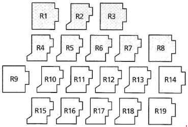
| Relay | ||
| R1 | Auxiliary heating | |
| R2 | Rear screen wiper | |
| R3 | Supply relay | |
| R4 | Relief relay | |
| R5 | — | |
| R6 | Direction indicator warning light | |
| R7 | Headlight washer | |
| R8 | Wiper/washer system (front) | |
| R9 | Chime | |
| R10 | Jumper for rear fog lights | |
| R11 | Horn | |
| R12 | Fuel pump (petrol) | |
| Glow plugs (diesel) | ||
| R13 | Light relay | |
| R14 | Heated rear screen | |
| R15 | Wiper relief relay | |
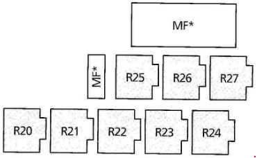
Additional relay box (under the instrument panel)
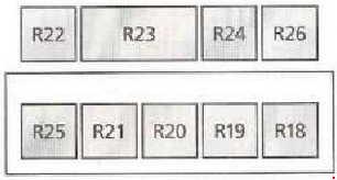
| Number | Relay |
| 18 | Auxiliary heating |
| 19 | Daytime running light |
| 20 | Freewheel lock |
| 21 | Rear vent windows |
| 22 | Heated front screen |
| 23 | Servotronic 4×4 |
| 24 | Window lifter relay |
| 25 | Cut-off relay |
| 26 | Warning timer unit |
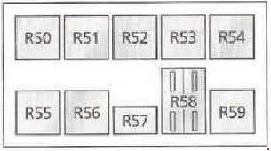
Engine compartment fuse box
| Number | Ampere Rating [A] | Description |
| 57 | 30 | Secondary blower |
| 58 | 40 | Cooling blower motor |
| 59 | 30 | Cooling blower castor |
| 40 | ||
| Relay | ||
| 50 | 3rd blower position | |
| 51 | Full throttle cut-off | |
| 52 | 2nd blower position | |
| 53 | Deceleration relay | |
| 54 | 1st blower position | |
| Water pump protection diodes | ||
| 55 | Automatic transmission | |
| 56 | Secondary blower | |
Type 2
| Fuse | Ampere Rating [A] | Description |
| 1 | 20 | Heated front seats |
| 2 | 10 | Electrically operated windows, electrically operated and heated mirrors, electrically operated rear vent windows |
| 3 | 5 | Digital dock,glove compartment light, sunroof, parking aid, thermo switch outside temperature, ABS, airconditioning Speed control, navigation system, central junction box |
| 4 | 10 | Engine management, engine immobilisation system, reversing light |
| 5 | 15 | Reversing light, automatic transmission, 4-wheel drive |
| 6 | 10 | Horn |
| 7 | 25 | Cigar lighter |
| 20 | ||
| 8 | 30 | Auxiliary heating, additional battery, trailer coupling |
| 9 | 30 | ABS |
| 10 | 30 | ABS |
| 11 | 20 | Headlamp washer |
| 12 | 15 | Digital clock, central locking, rear wiper, sunroof |
| 13 | 3 | Engine management, fuei shut-off relay |
| 14 | 10 | Fuel supply (diesel) |
| 20 | Fuel pump, ignition relay | |
| 15 | 30 | Cooling fan extended run (2.8 and diesel) |
| 16 | 30 | Thermo switch, cooling fan speed 1 |
| 17 | 10 | Automatic transmission |
| 30 | Glow plugs (diesel 66kw) | |
| 18 | 5 | Thermo switch, cooling fan speed 2, air conditioning, Instrument panel, cooling fan extended run |
| 19 | 5 | Central locking, telephone, instrument panel, diagnosis, radio, air conditioning, parking aid |
| 20 | 10 | Brake lights |
| 21 | 25 | Air conditioning |
| 30 | ||
| 22 | 25 | Air conditioning |
| 30 | ||
| 23 | 10 | Radio, CD changer |
| 24 | 25 | Booster heater (diesel) |
| 25 | 3 | Radio, telephone, seat belt warning tone, Central junction box |
| 26 | 30 | Starter, automatic transmission, ignition |
| 27 | 25 | Cooling fan extended run, air conditioning, rear and front blower, heated front screen, auxiliary heating |
| 28 | 10 | Water pump (V6), thermo switch coolant, ABS, Cooling fan extended run, air conditioning, wiper switch |
| 29 | 5 | Front wiper, heated washer jets, blower relay, Air conditioning, central junction box, auxiliary heating, heated front and rear screen, heated washer jets |
| 30 | 3 | Number plate light |
| 31 | 15 | Fron fog lights |
| 32 | 3 | Relay ignition, fuel pump, engine management, fuel pump shut-off relay, glow plugs (diesel) |
| 33 | 25 | Front screen wiper Auxiliary heating, additional battery, luggage compartment light, trailer coupling |
| 34 | 25 | Heater blower |
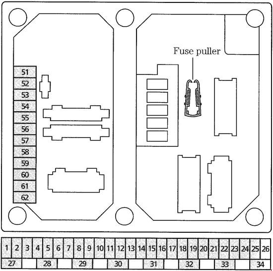
| Central fuse box (under the instrument panel level 1) | ||
| 51 | 20 | Heated rear screen, heated mirrors |
| 52 | 20 | Direction indicators |
| 53 | 10 | Consumer cut off relay (interior lights) |
| 54 | 10 | Alarm horn |
| 55 | 5 | Power supply on board electronics |
| 56 | 5 | Parking light right hand side |
| 57 | 5 | Parking light left hand side |
| 58 | 10 | Headlamp levelling, Daytime running lights (Scandinavia) |
| 59 | 10 | Dipped beam left hand side |
| 60 | 10 | Dipped beam right hand side |
| 61 | 10 | Main beam left hand side |
| 62 | 10 | Main beam right hand side |
Additional fuses (under drivers seat)
| Number | Ampere Rating [A] | Description |
| 76 | 15 | Luggage compartment sockets |
| 77 | 25 | Additional battery (if fitted) |
| 30 | ||
| Relay | ||
| 20 | Auxiliary heating | |
Central fuse box (under the instrument panel, level 2)
| Number | Circuits Protected |
| 1 | Cooling fan level 2 (2.0 i and 2.3 i DOHC engines) |
| Electrically operated mirrors (2.8 i CD-V6 engine) | |
| 2 | Cooling fan level 1 (2.0 i and 2.3 i DOHC engines) |
| Electrically operated mirrors (2.8 I CD-V6 engine) | |
| 3 | Inverter relay (2.0 i and 2.3 i DOHC engines) |
| Radio telephone (2.8 i CD-V6 and turbo diesel engines) | |
| Catalytic converter (2.8 i CD-V6 engine) | |
| 4 | Auxiliary heating, air conditioning |
| Belt warning buzzer (2.8 i CD-V6 engine) | |
| 5 | Engine cooling fan (2.8 i CD-V6 and turbo diesel engines) |
| 6 | Automatic transmission |
| 7 | Auxiliary heating, cooling fan level 2 |
| 8 | Headlamp washer |
| 9 | Daytime running lights (Scandinavia) |
| 10 | Horn |
| 11 | Full throttle shut off |
| 12 | Air conditioning |
| 13 | Blocking diode (2.8 i CD-V6 and turbo diesel engines) |
| 14 | Engine immobilisation system |
| 15 | Switch recirculated air (air conditioning and auxiliary heating) |
| 16 | Electrically operated rear vent windows |
| 17 | Auxiliary heating |
| 18 | Cooling system |
| Radio telephone (2.8 i CD-V6 engine) | |
| 19 | Blocking diode |
| Diesel relay (turbo diesel engine) |
Central fuse box (under the instrument panel, level 3)
| Number | Ampere Rating [A] | Description |
| * | 50 | Heated front screen |
| * | 30 | Electrically operated windows, electrically operated rear vent windows |
| * | 80 | Glow plugs (diesel engine) |
| * | 50 | Glow plugs (diesel engine) |
| * | 30 | Cooling fan level 2 |
| * | 40 | Cooling fan |
| * | 40 | Cooling fan |
| Relay | ||
| 20 | Auxiliary heating | |
| 21 | Wiper motor | |
| 22 | Secondary air injection | |
| Glow plug relay – stage 2 (turbo diesel engine) | ||
| 23 | Heated front screen | |
| 24 | Fuel pump (petrol engines) | |
| Glow plug relay (turbo diesel engine) | ||
| 25 | Air conditioning (2.0 i and 2.3 i DOHC engines) | |
| Glow plug relay – stage 1 (turbo diesel engine) | ||
| Cooling fan (2.8 i CD-V6 engine) | ||
| 26 | Starter power relay | |
| * The location of the maxifuses depends on the model. | ||
WARNING: Terminal and harness assignments for individual connectors will vary depending on vehicle equipment level, model, and market.