Ford Heavy-Duty Truck F-Max 12.7L Ecotroq (2018 – 2021) – fuse box diagram
Year of production: 2018, 2019, 2020, 2021
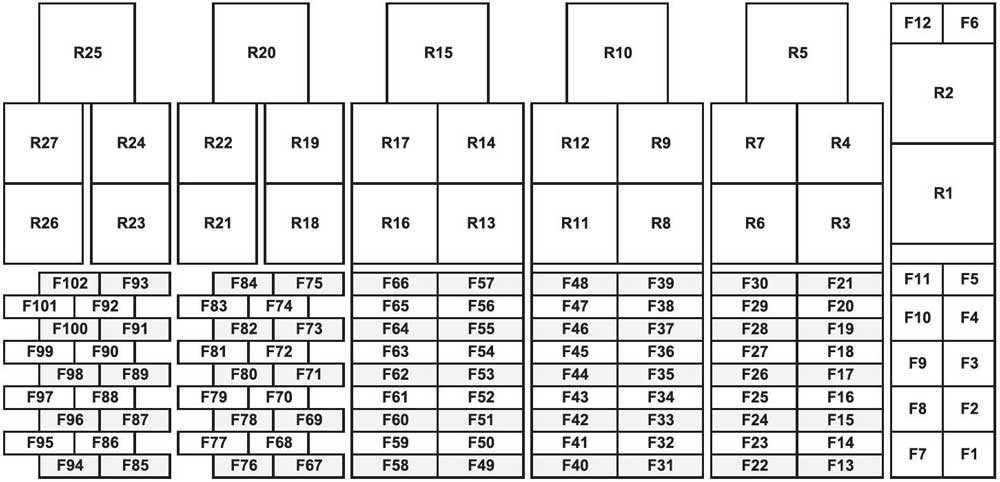
Fuse Box
| No. |
A |
Protected Component |
| 1 | 30 | Automatic Transmission Control Unit No.1 |
| 2 | 40 | Windshield Heating No.1 |
| 3 | 40 | Windshield Heating No.2 |
| 4 | 40 | Park Air Conditioner |
| 5 | – | – |
| 6 | 20 | 12V Power Outlet |
| 7 | 30 | Air Conditioner Fan |
| 8 | – | – |
| 9 | 50 | Cab Lifting Motor |
| 10 | 30 | 24V KL30 (Horn and A/C Motor Relay) |
| 11 | 40 | 24V Power Outlet Panel and Bed |
| 12 | – | – |
| 13 | 20 | Engine Control Unit |
| 14 | 10 | Automatic Transmission Control Unit No.2 |
| 15 | 7.5 | Intarder |
| 16 | 15 | Parking Lamps |
| 17 | 5 | Tachograph |
| 18 | 3 | Front Camera |
| 19 | 7.5 | Door Lock Button |
| 20 | 20 | Body Control Unit No.1 |
| 21 | 5 | Electronic Air Pressure Unit |
| 22 | 20 | Body Control Unit No.2 |
| 23 | 10 | Brake Lamps |
| 24 | 7.5 | Refrigerator |
| 25 | 20 | Body Control Unit No.3 |
| 26 | 20 | NOx Sensors 1 & 2 & Urea Quality and Level Sensor |
| 27 | 20 | Wet Type Heater |
| 28 | 10 | Mirror Heaters |
| 29 | 7.5 | Triple Dome Parking Lamps & Dome Beacon |
| 30 | 10 | Dry Type Heater |
| 31 | 30 | 7 Pin Trailer Connector |
| 32 | 3 | ERA Glonass Emergency Call Unit |
| 33 | 20 | Body Control Unit No.4 |
| 34 | 20 | Body Control Unit No.5 |
| 35 | 20 | Body Control Unit No.6 |
| 36 | 20 | Body Control Unit No.7 |
| 37 | 3 | Right and Left ARM |
| 38 | 10 | OBD (On Board Diagnosis System) Connectors 1 & 2 |
| 39 | 20 | Body Control Unit No.8 |
| 40 | 7.5 | Shade Motor |
| 41 | 25 | Convertor No.2 |
| 42 | 5 | Map Assisted Speed Control Unit |
| 43 | 15 | Horn |
| 44 | 15 | EBS Unit |
| 45 | 3 | Buttons |
| 46 | 25 | Convertor No.2 |
| 47 | 15 | Denox Control Unit and Urea Heaters |
| 48 | 20 | After Sales Chassis and Dome Connectors |
| 49 | – | – |
| 50 | 20 | 24V Power Outlet – Panel |
| 51 | 20 | 24V Power Outlet – Bed |
| 52 | 20 | After Sales Cab Connector & Fleet Monitoring Unit |
| 53 | 15 | Lighter |
| 54 | 5 | Tire Pressure Display Unit |
| 55 | 5 | Ignition Switch |
| 56 | 10 | Instrument Panel |
| 57 | 3 | Exterior Cabinet Lamps |
| 58 | 3 | Engine RPM |
| 59 | 10 | 15-pin Trailer Connector & After Sales Chassis and Dome Connectors – Park |
| 60 | 5 | Vehicle Park Lamps |
| 61 | 1 | Sunroof Window (Headlining Console Side) Button – Waking |
| 62 | 1 | Sunroof Window (bed Side) Button – Waking |
| 63 | 1 | Bed Lamp Button – Waking |
| 64 | 3 | Tachograph (for Vehicles Carrying Dangerous Goods) |
| 65 | – | – |
| 66 | 5 | Interior Cabinet Lamps & Door Locking Buttons |
| 67 | 7.5 | EBS Unit (Ignition) |
| 68 | 3 | Instrument Panel (Ignition) |
| 69 | 3 | Electronic Air Pressure Unit (Ignition) |
| 70 | 7.5 | Intarder (Ignition) |
| 71 | 7.5 | Tachograph (Ignition) |
| 72 | 3 | Lane Departure Warning System Buzzer |
| 73 | 7.5 | Radar & Camera & Map Assisted Speed Control Unit (Ignition) |
| 74 | 7.5 | Automatic Transmission Control Unit (Ignition) |
| 75 | 5 | Engine Control Unit (Ignition) |
| 76 | 3 | Electronically Air Suspension Control |
| 77 | 10 | Seat Heater |
| 78 | – | – |
| 79 | 3 | Brake Lamps |
| 80 | 15 | After Sales Chassis and Dome Connectors & Fleet Monitoring Unit (Ignition) |
| 81 | 3 | ERA Glonass Emergency Call Unit (Ignition) |
| 82 | 7.5 | Working Lamp (Ignition) |
| 83 | 3 | Right and Left ARM (Ignition) |
| 84 | 5 | Buttons & Steering Lock Valve (Ignition) |
| 85 | 10 | Reversing Lamps |
| 86 | – | – |
| 87 | 20 | Fuel Heater |
| 88 | 7.5 | 7-pin Trailer Connector (Ignition) |
| 89 | 3 | Convertors 1 & 2 (Ignition) |
| 90 | 10 | NOx Sensors 1 & 2 |
| 91 | 7.5 | Urea Quality and Level Sensor |
| 92 | 15 | Turbo & Exhaust Gas Recirculation |
| 93 | 7.5 | Front Headlamp Leveling Motor & Rain Sensor & in-Vehicle Temperature and Humidity Sensor |
| 94 | 5 | Window and Mirror Button |
| 95 | – | – |
| 96 | – | – |
| 97 | 20 | Body Control Unit (12V Supply) |
| 98 | 7.5 | A/C Control Unit |
| 99 | 7.5 | Exterior Cabinet Lamps |
| 100 | 3 | Headlamp Switch |
| 101 | 7.5 | Horn and A/C Motor Relay Coil (+) |
| 102 | 20 | Radio |
| Relay | ||
| R1 | 40 | Ignition/Start No.1 |
| R2 | 40 | Ignition/Start No.2 |
| R3 | 20 | 12V: Power Outlets (Sealed Relay) |
| R4 | 20 | Lighting Working Lamp |
| R5 | 40 | Ignition/Accessory |
| R6 | 20 | Shade Motor (Up) |
| R7 | 20 | Engine Off |
| R8 | 20 | Horn |
| R9 | 20 | Urea Module and Urea Heaters |
| R10 | 40 | A/C Motor |
| R11 | 20 | Reverse Lamps & Reverse Warning |
| R12 | 20 | Urea Quality and Level Sensor & NOx Sensors & Turbo & Exhaust Gas Recirculation |
| R13 | – | – |
| R14 | – | – |
| R15 | 40 | Cab Lifting Motor |
| R16 | – | – |
| R17 | 20 | Brake Lamps |
| R18 | – | – |
| R19 | 20 | Parking Lamps |
| R20 | 40 | Windshield Heating No.1 |
| R21 | 20 | Triple Dome Park Lamps |
| R22 | – | – |
| R23 | 20 | Dome Beacon |
| R24 | 20 | Mirror Heaters |
| R25 | 40 | Windshield Heating No.2 |
| R26 | 20 | Door Locking Buttons |
| R27 | 20 | Shade Motor (Down) |
Fusible Link Block
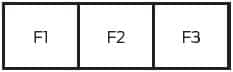
| No. |
A |
Protected Component |
| 1 | – | – |
| 2 | 150 | Alternator |
| 3 | 175 | Grilled Heater |
WARNING: Terminal and harness assignments for individual connectors will vary depending on vehicle equipment level, model, and market.