Ford Mustang (2005 – 2009) – fuse box diagram
Year of production: 2005, 2006, 2007, 2008, 2009
Passenger Compartment Fuse Panel
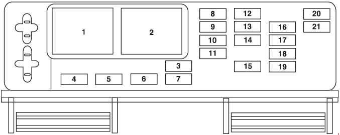
| Fuse | Ampere rating [A] | Description |
| 3 | 10 | Wiper power/Blower motor relay |
| 4 | 5 | Power mirrors |
| 5 | — | — |
| 6 | 5 | Accessory delay feeds |
| 7 | 10 | 2005: Overdrive cancel 2006, convertible: Overdrive cancel 2007-2009: Electrochromic mirror |
| 5 | 2006, coupe: Overdrive cancel | |
| 8 | 10 | Cluster, Data Link Connector (DLC) |
| 9 | — | — |
| 10 | 5 | Intrusion Sensing Module (15M), Climate control |
| 11 | — | — |
| 12 | 5 | Climate control. Ignition |
| 13 | — | — |
| 14 | 5 | A/C cycle switch |
| 15 | 10 | Brake On/Off (BOO) power |
| 16 | 5 | Cluster |
| 17 | 10 | Restraint Control Module (RCM), Passenger Occupant Detection System (PODS), Passenger Air bag Deactivation Indicator (PADI) |
| 18 | 10 | Anti-lock Brake System (ABS), Positive Crankcase Ventilation (PCV) valve heater (2005-2006), Ignition (2005-2006 |
| 19 | 5 | Powertrain Control Module (PCM) relays, Passive Anti-Theft System (PATS), Instrument cluster airbag warning lamp (2007-2009) |
| 20 | 10 | Radio (Start) |
| 21 | 10 | Starter relay |
| Relay | ||
| 1 | Accessory delay #1 | |
| 2 | — | |
Power Distribution Box
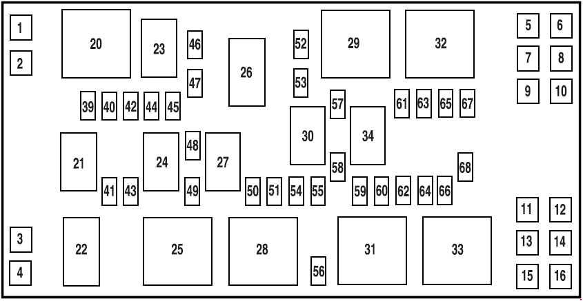
| Number | Ampere rating [A] | Description |
| 1 | — | — |
| 2 | 30 | Climate control blower |
| 3 | 40 | Cooling fan |
| 4 | 30 | Starter |
| 5 | 30 | 2005: Right front window motor 2006-2009: Left front window motor |
| 6 | 30 | Rear amplifier (Shaker 1000 radio) |
| 7 | 30 | 2005: Left front window motor 2006-2009: Right front window motor |
| 8 | 40 | Anti-lock Brake System (ABS) #1 |
| 9 | 30 | Rear amplifier (Shaker 1000 radio) |
| 10 | 30 | Wipers |
| 11 | 30 | Left rear window motor (Convertible only) |
| 12 | 30 | Right rear window motor (Convertible only) |
| 13 | 40 | Convertible top |
| 14 | 30 | 2005-2006: Seat 2007-2009: Driver seat |
| 15 | 30 | 2007-2009: Passenger seat |
| 16 | 30 | Front amplifier (Shaker 500 radio) |
| 39 | 15 | 2007-2009: Engine #4 |
| 40 | 15 | Engine #2 |
| 41 | 15 | Fuel pump |
| 42 | 15 | Engine #3 |
| 43 | 10 | Alternator |
| 44 | 10 | Delayed accessory |
| 45 | 10 | PCM |
| 46 | 25 | Horn |
| 47 | 15 | Engine #1 |
| 49 | 15 | A/C clutch |
| 50 | 15 | High beams |
| 51 | 10 | Convertible top |
| 52 | 30 | Rear defroster |
| 54 | 10 | 2005-2006: PCM delay |
| 20 | 2008-2009: Left HID headlamp | |
| 55 | 20 | 2008-2009: Right HID headlamp |
| 56 | 20 | Radio, SDARS (2007-2009) |
| 57 | 20 | Decklid release |
| 58 | 15 | Fog lamps |
| 59 | 30 | SJB #5 (Instrument panel fuse box) |
| 60 | — | — |
| 61 | 20 | Power point #1 (Instrument panel) |
| 62 | 20 | SJB #7 (Instrument panel fuse box) |
| 63 | 30 | SJB #6 (Instrument panel fuse box) |
| 64 | 20 | Power point #2 (Console) |
| 65 | 30 | ABS #2 |
| 66 | 25 | 2007-2009: Heated seats |
| 67 | 30 | SJB #4 (Instrument panel fuse box) |
| 68 | 20 | Ignition |
| Relay | ||
| 20 | PCM #2 | |
| 21 | Fuel pump | |
| 22 | Starter | |
| 23 | 2005-2006: PCM #1 | |
| 24 | A/C clutch | |
| 25 | Cooling fan (High-speed) | |
| 26 | Horn | |
| 27 | High beams | |
| 28 | Cooling fan (Low-speed) | |
| 29 | Rear defroster | |
| 30 | Fog lamps | |
| 31 | Convertible top (Up) | |
| 32 | Climate control blower | |
| 33 | Convertible top (Down) | |
| 34 | 2006-2009: Decklid | |
| Diode |
||
| 48 | 2005-2008: A/C clutch | |
| 53 | PCM | |
Auxiliary relay with HID headlamps (2008-2009)
On vehicles equipped with HID headlamps, an auxiliary relay box is located under the hood on the right hand side front of the engine compartment. This auxiliary relay box contains the left front and right front HID headlamp relays.
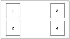
| Number | Description |
| 1 | Left HID headlamp |
| 2 | Right HID headlamp |
| 3 | — |
| 4 | — |
WARNING: Terminal and harness assignments for individual connectors will vary depending on vehicle equipment level, model, and market.