Ford Thunderbird (1989 – 1993) – fuse box diagram
Year of production: 1989, 1990, 1991, 1992, 1993
Passenger Compartment Fuse Box
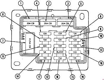
| Number | Ampere rating [A] | Description |
| 1 | 20 | Circuit Breaker: Power Window, Moonroof, Luggage Compartment Release |
| 2 | 20 | Circuit Breaker: Power Seat, Power Door Locks, Lumbar Seat, Fuel Filler Door |
| 3 | 20 | Circuit Breaker: Cigar Lighter, Flash to Pass |
| 4 | 10 | Anti-theft, Chime, LCD Illumination Relay, Autolamps |
| 5 | 15 | Radio, Power Antenna, CD Player |
| 6 | 15 | Stop Lamps, Speed Control, ABS |
| 7 | 8,25 | Circuit Breaker: Windshield Wiper/Washer |
| 8 | 15 | Fog Lamps |
| 9 | 15 | HEGO Sensors |
| 10 | 10 | Backup Lamps, Flasher Unit |
| 11 | 30 | A/C Heater Blower |
| 12 | 15 | Steering Sensor, Daytime Running Lamps, Washer Level Sensor, A/C Heater Function Switch, Keyless Entry, Illuminated Entry, Automatic Day/Night Mirror, Instrument Cluster, Rear Defogger Switch, Engine Coolant Level Sensor, Vehicle Maintenance Monitor, Variable Assist Power Steering (VAPS), Programmed Ride Control |
| 13 | 15 | Anti-lock Brake Motor Relay |
| 14 | 5 | Instrument Illumination, LCD Relay |
| 15 | — | — |
| 16 | 10 | Rear Exterior Lamps |
| 17 | 15 | Main Lights Switch, Front Exterior Lamps |
| 18 | 15 | Courtesy lamps, Power Mirror, Main Light Switch, Daytime Running Lamps, Engine Compartment Lamp |
| 19 | 10 | Instrument Cluster, Chime, Anti-lock, Passive Restraint, Autolamp, Anti-theft |
Engine Compartment Fuse Box
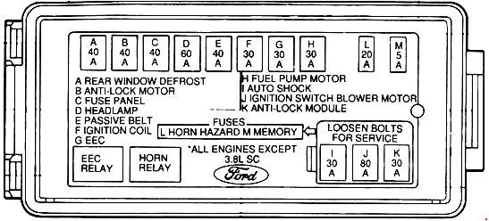
| Number | Ampere rating [A] | Description |
| A | 40 | Rear Window Defrost |
| B | 40 | ABS Hydraulic Pump Motor |
| C | 30 | Radio, Anti-theft, Fuse No.: 6 (Stop Lamps, Speed Control, ABS), 3 (Cigar Lighter, Flash to Pass), 2 (Power Seat, Power Door Locks, Lumbar Seat, Fuel Filler Door), |
| D | 60 | Headlamps, Courtesy lamps |
| E | 40 | Passive Restraint |
| F | 30 | Ignition Coil, EEC Relay, Sensors |
| G | 30 | Electronic Control Assembly, Engine Sensors |
| H | 30 | Fuel Pump |
| I | 30 | Programmed Ride Control |
| J | 80 | Ignition Switch |
| K | 30 | Anti-lock Brake System |
| L | 20 | Horn, Hazard Flasher, Turn Signal |
| M | 5 | Radio, Vehicle Maintenance Monitor, Electronic Cluster |
WARNING: Terminal and harness assignments for individual connectors will vary depending on vehicle equipment level, model, and market.