Genesis G70 (2021 – 2023) – fuse box diagram (UK version)
Year of production: 2021. 2022, 2023
Passenger compartment fuse box
The fuse panel is located in the driver’s side panel bolster.
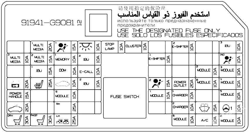
| Fuse Name | Amps | Circuit Protected |
|---|---|---|
| MULTI MEDIA 1 | 20A | W/O ISG: Fuse – F11, F12 With ISG: Low DC-DC Converter (Audio) |
| AIRBAG 1 | 15A | SRS Control Module |
| ROOM LAMP | 10A | Overhead Console Lamp, Center Room Lamp, Room Lamp Vanity Lamp Switch LH/RH, Luggage Lamp LH/ RH Glove Box Lamp, Driver/Passenger Foot Lamp |
| STOP LAMP | 10A | IBU, Stop Lamp Switch |
| CLUSTER | 10A | Instrument Cluster, Head-Up Display |
| E-SHIFTER 2 | 10A | Electronic ATM Shift Lever |
| IBU 3 | 10A | IBU |
| MULTI MEDIA 3 | 10A | With ISG: Instrument Cluster, Head-Up Display, A/C Switch Front Wireless Charger, Around View Monitor [W/O ISG]: Around View Monitor ECU |
| MULTI MEDIA 2 | 15A | Audio |
| MEMORY 1 | 10A | A/C Control Module, A/C Switch, Security Indicator Head-Up Display, Power Tail Gate Unit, Power Trunk Module [W/O ISG] Instrument Cluster |
| IBU 4 | 10A | IBU |
| E-SHIFTER 1 | 10A | Electronic ATM Shift Lever |
| AIRBAG IND. | 10A | Instrument Cluster, Overhead Console Lamp |
| IBU 1 | 15A | IBU, Driver/Passenger Smart Key Outside Handle, Driver/Passenger Power Outside Mirror |
| DRIVER DR MODULE | 10A | Driver Door Module, Driver/Passenger Power Outside Mirror |
| E-CALL | 10A | Emergency Call Module |
| MODULE 2 | 10A | IBU |
| MODULE 3 | 10A | Driver Door Module, Stop Lamp Switch |
| DOOR LOCK | 20A | Door Lock Relay, Door Unlock Relay, Dead Lock Relay |
| SEAT HEATER | 25A | Front Air Ventilation Seat Control Module Front Seat Warmer Control Module |
| TRUNK | 10A | Trunk Lid Relay, Fuel Lid Relay, Crash Pad Switch |
| IBU 2 | 10A | IBU, Rain Sensor |
| AIRBAG 2 | 15A | SRS Control Module |
| POWER OUTLET 1 | 20A | Front Power Outlet |
| MODULE 8 | 10A | Cooling Fan Controller (BLDC Motor) |
| MODULE 7 | 10A | Dosing Control Module, AWD ECM, Active Air Flap LH, ECS Unit, Front View Camera, Console Switch, Crash Pad Switch, IBU, Console Switch, Front View Camera, Front Wireless Charger, Steering Tilt & Telescopic Module, Surround View Monitor ECU, Electronic Control Engine Mounting Module, Steering Angle Sensor |
| POWER HANDLE | 15A | Steering Tilt & Telescopic Module |
| MODULE 9 | 10A | Driver Air Lumbar Control Unit |
| MODULE 1 | 10A | Data Link Connector, Console Switch, Hazard Switch,Electronic Control Engine Mounting Module |
| CHARGER | 10A | Front/Rear USB Charger, Front Tray USB Charger |
| MODULE 5 | 10A | A/C Control Module, A/C Switch, A/V & Navigation Head Unit, Low DC-DC Converter (Audio/AMP), Electro Chromic Mirror, AMP, Emergency Module, Driver IMS Control Module, Front Air Ventilation Seat Control Module, Data Link Connector, Front/Rear Seat Warmer Control Module, IFS Module |
| SUNROOF | 20A | Sunroof Control Unit (Glass) |
| PASSENGER P/ WINDOW | 25A | Passenger Safety Power Window Module, Rear Power Window Switch RH, Rear Safety Power Window Module RH |
| POWER OUTLET 2 | 20A | [5DR] Rear Power Outlet |
| WASHER | 15A | Multifunction Switch |
| MDPS | 10A | MDPS Unit |
| DRIVER P/SEAT | 30A | Driver IMS Control Module, Driver Seat Manual Switch |
| PASSENGER P/SEAT | 30A | Passenger Seat Manual Switch, Passenger Walk In Relay Module |
| DRIVER P/WINDOW | 25A | Driver Safety Power Window Module, Rear Safety Power Window Module LH, Rear Power Window Switch LH |
| MODULE 6 | 10A | Surround View Monitor ECU, IBU, Emergency Call Module, AMP, Electronic ATM Shift Lever, Overhead Console Lamp, A/V & Navigation Head Unit, Low DC-DC Converter (Audio/AMP) |
| A/CON | 10A | A/C Control Module, A/C Switch, PM Sensor (A/C), E/R Junction Block (RLY.6), Diesel Junction Block (RLY.3/4) |
| MODULE 4 | 10A | Head Lamp LH/RH, Auto Head Lamp Leveling Device Module |
| IF43 | Dark current switch | Left front seat connector (memory seat module) / GWM / HVAC control unit/mobile phone WCM |
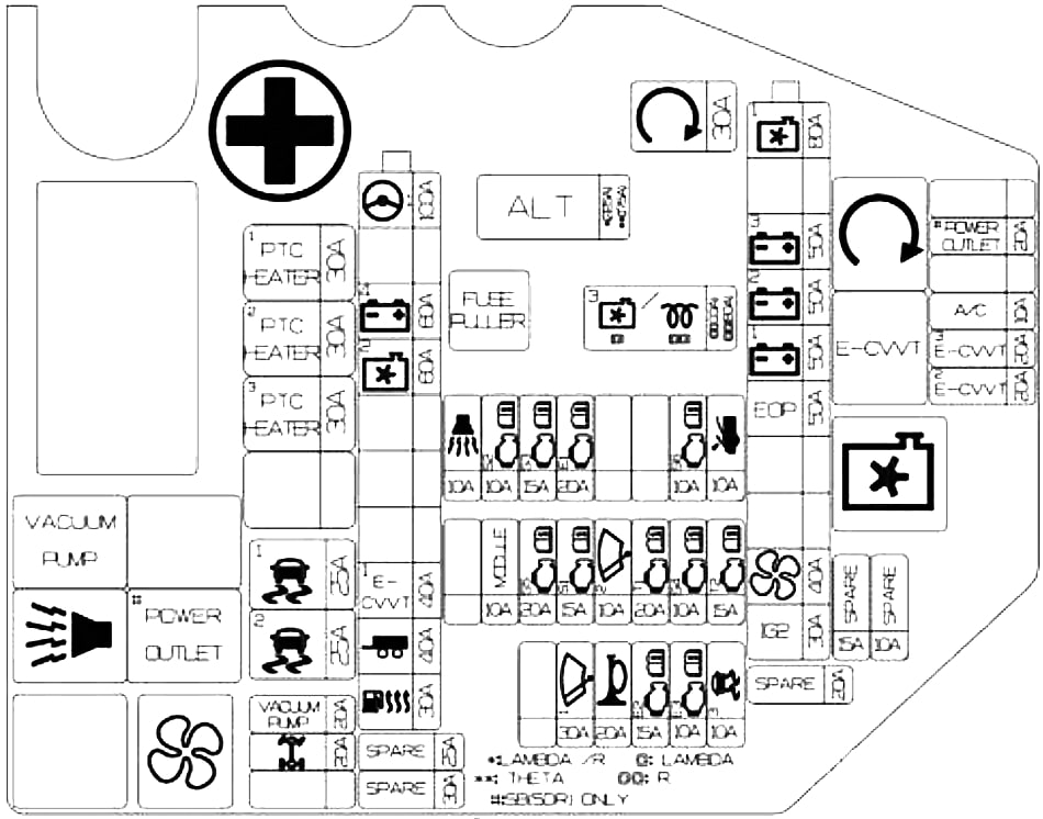
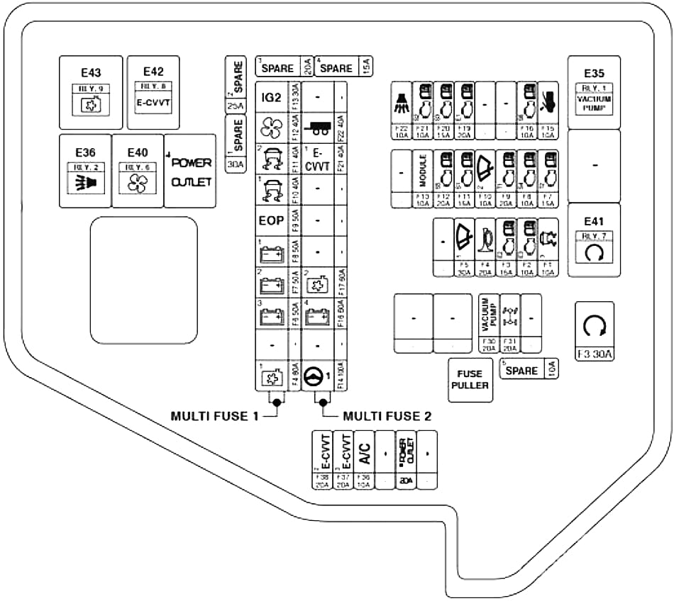
Engine Compartment Fuse Box
Left-hand drive vehicles
| Fuse Name | Symbol | Amps | Circuit Protected |
|---|---|---|---|
| ALT | 175A / 225A | Alternator, Fuse – F2, Multi Fuse 1 – F4, F6, F7, F8, F9, F10, F11, F12, F13 | |
| C/FAN 3 | 3 |
125A | G6DP – BLDC Motor: Cooling Fan Controller |
| GLOW | 125A | D4HB: Glow Relay Unit | |
| START | 30A | RLY. 7 (Start Relay) | |
| C/FAN 1 | 80A | BLDC Motor: Cooling Fan Controller | |
| B+ 3 | 50A | ICU Junction Block (Fuse – F5, Leak Current Autocut Device Fuse – F2, F4, F13, F14, F21, F22) | |
| B+ 2 | 50A | ICU Junction Block (Fuse – F27, F35, F43, F51, F52) | |
| B+ 1 | 50A | ICU Junction Block (Fuse – F28, F29, F37, F45, F53) | |
| EOP | EOP | 50A | [With ISG] Electric Oil Pump Module |
| ESP 1 |  |
40A | ESP Control Module |
| ESP 2 |  |
40A | ESP Control Module |
| BLOWER | 40A | RLY. 6 (Blower Relay) | |
| IG2 | 30A | PCB Block (IG2 Relay) | |
| MDPS | 100A | MDPS Unit | |
| B+ 4 | 60A | PCB Block (Engine Control Relay, Fuse – F4, F5, F13, F22) | |
| C/FAN 2 | 60A | DC Motor: RLY. 9 (Cooling Fan Relay) | |
| E-CVVT 1 | 40A | G4KL: RLY. 8 (E-CVVT Relay) | |
| TRAILER | 40A | Trailer Connector | |
| FUEL HEATER | 40A | Diesel Junction Block (RLY.1 (Fuel Filter Heater Relay)) | |
| PTC HEATER1 | 30A | Diesel Junction Block (RLY.2 (PTC Heater #1 Relay)) | |
| PTC HEATER2 | 30A | Diesel Junction Block (RLY.3 (PTC Heater #2 Relay)) | |
| PTC HEATER3 | 30A | Diesel Junction Block (RLY.4 (PTC Heater #3 Relay)) | |
| VACUUM PUMP |  |
20A | G4KL/G6DP: RLY. 1 (Vacuum Pump Relay) |
| AWD | 20A | AWD ECM | |
| A/CON | A/C | 10A | A/C Control Module |
| E-CVVT 3 | 20A | G4KL: ECM | |
| E-CVVT 2 | 20A | G4KL: ECM |
Right-hand drive vehicles
| Fuse Name | Symbol | Amps | Circuit Protected |
|---|---|---|---|
| START | 30A | RLY. 7 (Start Relay) | |
| C/FAN 1 | 80A | BLDC Motor: Cooling Fan Controller | |
| B+ 3 | 50A | ICU Junction Block (Fuse – F5, Leak Current Autocut Device Fuse – F2, F4, F13, F14, F21, F22) | |
| B+ 2 | 50A | ICU Junction Block (Fuse – F27, F35, F43, F51, F52) | |
| B+ 1 | 50A | ICU Junction Block (Fuse – F28, F29, F37, F45, F53) | |
| EOP | EOP | 50A | [With ISG] Electric Oil Pump Module |
| ESP 1 | |
40A | ESP Control Module |
| ESP 2 | |
40A | ESP Control Module |
| BLOWER | 40A | RLY. 6 (Blower Relay) | |
| IG2 | 30A | PCB Block (IG2 Relay) | |
| MDPS | 100A | MDPS Unit | |
| B+ 4 | 60A | PCB Block (Engine Control Relay, Fuse – F4, F5, F13, F22) | |
| C/FAN 2 | 60A | DC Motor: RLY. 9 (Cooling Fan Relay) | |
| E-CVVT 1 | 40A | G4KL: RLY. 8 (E-CVVT Relay) | |
| TRAILER | 40A | Trailer Connector | |
| AWD | 20A | AWD ECM | |
| A/CON | A/C | 10A | A/C Control Module |
| E-CVVT 3 | 20A | G4KL: ECM | |
| E-CVVT 2 | 20A | G4KL: ECM | |
| ESC3 | 10A | ECM | |
| ECU3 | 10A | ESP Control Module | |
| ECU2 | 15A | ECM | |
| HORN | 20A | Horn Relay | |
| WIPER1 | 30A | Wiper Power Relay | |
| TCU2 | 15A | P/N Relay, TCM | |
| SENSOR4 | 10A | Electronic Oil Pump Module, Brake Vaccum Switch, E/R Junction Block (RLY.1 (Brake Vacuum Relay) | |
| TCU1 | 20A | TCM | |
| WIPER2 | 10A | IBU, ECM | |
| SENSOR1 | 15A | Rear Sub Junction Block (Fuel Pump Relay); [D4HB] Rail Pressure Regulating Valve, Diesel Junction Block (RLY.1 (Fuel Filter Heater Relay) | |
| SENSOR5 | 20A | [G4KL] Ingition Coil #1/#2/#3/#4; [G6DP] Ignition Coil #1/#2/#3/#4/#5/#6; [D4HB] Electronic Water Pump | |
| MODULE | MODULE | 10 | Active Air Flap LH |
| ACTIVE HOOD |  |
10 | Active Hood Lift Control Module |
| SENSOR1 | 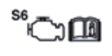 |
10A | [D4HB] Głów Relay Unit, Fuel Heater & Water Separator Sensor |
| ECU1 | 20A | ECM | |
| SENSOR3 | 15A | [G4KL] Oxygen Sensor (Up/Down) [G6DP] Oxygen Sensor #1/#2/#3/#4 [D4HB] Lamba Sensor #1/#2. Electronic VGT Actuator, Fuel Metering Unit, EGR Cooing Bypass Solenoid Valve, PTC Heater, Mid Nox Sensor, PM Sensor, Rear Nox Sensor | |
| SENSOR2 | 10A | E/R Junction Block (RLY.9 – Cooling Fan Relay); [G4KL] Electronic Thermostat, Oil Control Valve, Purge Control Solenoid Valve, Recirculation Control Solenoid Valve; [G6DP] Electronic Thermostat Oil Pressure Solenoid Valve; Oil Control Valve #1/#2/#3/#4 (Intake/Exhaust), Recirculation Control Solenoid Valve, Purge Control Solenoid Valve, Variable Exhaust Flap Actuator LH/RH; [D4HB] Oil Pump Solenoid Valve, Air Flow Sensor, Crankshaft Position Sensor, Front Nox Sensor, Oil Level Sensor, Stop Lamp Switch | |
| B/ALARM | 10A | E/R Junction Block (RLY.2 – Burglar Alarm Horn Relay) |
Relay
| Type | Relay No. | Symbol | Relay Name |
|---|---|---|---|
| MICRO | RLY.1 | Vacuum Pump Relay | |
| MICRO | RLY.2 | Burglar Alarm Horn Relay | |
| MICRO | RLY.6 | Blower Relay | |
| MICRO | RLY.7 | Start Relay | |
| MICRO | RLY.8 |  |
E-CVVT Relay (G4KL) |
| MINI | RLY.9 | Cooling Fan Relay |
Trunk Fuse Box Diagram
| Fuse Name | Symbol | Amps | Circuit Protected |
|---|---|---|---|
| DCU 2 |  |
15A | Dosing Control Module |
| DCU 3 |  |
15A | Dosing Control Module |
| REAR WIPER | 15A | Wipre RR Relay, Rear Wiper Motor | |
| ECS | ECS | 15A | ECS Unit |
| POWER TRUNK | 30A | Power Trunk Module, Power Tailgate Unit | |
| DCU 1 |  |
15A | Dosing Control Module |
| FUEL PUMP | 20A | Fuel Pump Relay | |
| HEAT MIRROR | 10A | A/C Switch, Driver/Passenger Power Outside Mirror | |
| AMP 2 |  |
25A | AMP |
| REAR S/HEAT |  |
20A | Rear Seat Warmer Control Module |
| AMP 1 |  |
30A | W/O ISG: Fuse – F9 With ISG: Low DC-DC Converter (AMP) |
| IG1 | 15A | PCB Block (IG1 Relay) | |
| ACC | ACC | 30A | ICU Junction Block (Fuse – F32, F40, F54) |
| B+ 1 | 40A | ICU Junction Block (IPS5, IPS6, IPS7, IPS8, IPS9, IPS10, Fuse – F20, 30F) | |
| B+ 2 | 40A | ICU Junction Block (IPS1, IPS2, Fuse – F15, F39) | |
| REAR HEATED | 30A | Rear Heated Relay |
Battery junction block
| Fuse Name | Symbol | Amps | Circuit Protected |
|---|---|---|---|
| B+ 1 | 100A | Rear Sub Junction Block (ACC Relay, Fuse – F7, F12, F13, F16, F17) | |
| B+ 2 | 100A | Rear Sub Junction Block (DCU Relay, Fuse – F3, F5, F4, F11, F15) | |
| START | 40A | E/R Junction Block (Fuse – F3), PCB Block (Fuse – F3, F9) | |
| AMS | 10A | Battery Sensor |