Honda Civic (1996 – 2000) – fuse box diagram
Year of production: 1996, 1997, 1998, 1999, 2000
Passenger compartment
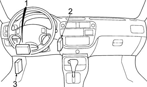
- Fuse Box
- Interlock Control Unit
- Transmission Control Module (TCM/CVT)
Keyless Door Lock Control Unit
Passenger compartment fuse box
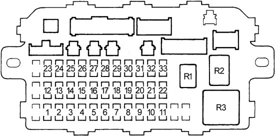
| No. | A | Circuits |
| 1 | — | — |
| 2 | — | — |
| 3 | 10 | Rear Wiper, Security System |
| 4 | 10 | Right Headlight (High Beam), Daytime Runing Lights (DRL) Control Unit |
| 5 | 10 | Left Headlight (High Beam), Daytime Runing Lights (DRL) Control Unit |
| 6 | Security System | |
| 7 | 20 | Left Rear Window Motor |
| 8 | 20 | Right Rear Window Motor |
| 9 | 15 | ‘98-‘00 (except GX): Ignition Coil |
| 10 | 20 | Front Passenger’s Window Motor |
| 11 | 20 | Driver’s Window Motor |
| 12 | 7,5 | Hazard Warning Switch |
| 13 | 15 | PGM-FI Main Relay, Supplemental Restraint System (SRS) Unit |
| 14 | 7,5 | Stereo Radio Tuner (’96-’98), Cruise Control Main Switch, Keyless Door Lock Control Unit (’99-’00) |
| 15 | 7,5 | Electrical Load Detector (ELD) Unit, Gauge Assembly, Transmission Control Module – TCM (’96-’98 CVT), PGM-FI, Vehicle Speed Sensor (VSS) |
| 16 | 7,5 | Rear Window Defogger (’96-’98), ABS Control Unit, Power Mirror Switch (’99-’00) |
| 17 | 7,5 | Power Mirrors (’96-’98), Air Delivery, Blower Controls, A/C Compressor Controls, Fans |
| 18 | 7,5 | Daytime Runing Lights (DRL) Control Unit |
| 19 | 7,5 | Back-Up Lights |
| 20 | 7,5 | Daytime Runing Lights (DRL) Control Unit |
| 21 | 10 | Right Headlight (Low Beam) |
| 22 | 10 | Left Headlight (Low Beam) |
| 23 | 10 | Supplemental Restraint System (SRS) Unit |
| 24 | 7,5 | Power Window Relay, Moonroof |
| 25 | 7,5 | Integrated Control Unit, Interlock System, Gauge Assembly |
| 26 | 20 | Front Wiper/Washer |
| 27 | 10 | ’96-’98: Accessory Power Socket |
| 15 | ’99-’00: Accessory Power Socket | |
| 28 | 10 | ’96-’97: Stereo Radio Tuner |
| 15 | ’98: Stereo Radio Tuner | |
| 10 | ’99-’00: Audio Unit | |
| 29 | — | — |
| 30 | 7,5 | Dash & Console Lights |
| 31 | 7,5 | PGM-FI Main Relay, Powertrain/Engine Control Module (PCM/ECM), Integrated Control Unit |
| 32 | 7,5 | Parking Lights, License Plate Lights, Tail Lights |
| 33 | 7,5 | Interlock System |
| Relay | ||
| R1 | Rear Window Defogger | |
| R2 | Power Window | |
| R3 | Turn Signal / Hazard |
|
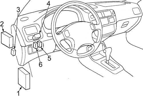
- Injector Control Module
- Cruise Control Unit
- Fuel Injector Relay
- Dash Lights Brightness Controller
- Starter Cut Relay
- Horn Relay
Engine Compartment
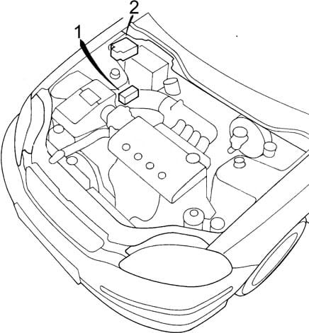
- Relay Box
- Fuse Box
Engine Compartment Fuse Box

| No. | A | Circuits |
| 41 | 80 | Power Distribution |
| 42 | 40 | Ignition Switch (BAT) |
| 43 | 7,5 | Ceiling Light, Data Link Connector |
| 44 | 20 | GX: PGM-FI Main Relay, Injector Control Module (Fuel Injector Relay) |
| 15 | except GX: PGM-FI Main Relay, Injector Control Module (Fuel Injector Relay) | |
| 45 | — | — |
| 46 | 40 | Power Window Motors (Power Window Relay) |
| 47 | 7,5 | Audio Unit (’99-’00), Clock, PCM (VBU), Stereo Audio Tuner (’96-’98), Transmission Control Module (’96-’98), Heater Control Panel |
| 48 | 30 | Combination Light Switch (Headlight), Fuse: No.33 |
| 49 | — | — |
| 50 | 30 | Rear Window Defogger (Rear Window Defogger Relay) |
| 51 | 20 | Power Door Lock Control Unit (’99-’00), Keyless Door Lock Control Unit (’99-’00), Moonroof |
| 52 | 15 | Horn System, Brake Lights, Brake Signal |
| 53 | 10 | Hazard Warning Light, Turn Signal/Hazard Relay |
| 54 | 40 | Security System (Option) |
| 55 | 40 | Blower Motor (Blower Motor Relay) |
| 56 | 20 | Condenser Fan Motor (Condenser Fan Relay), A/C Compressor Clutch (A/C Compressor Clutch Relay) |
| 57 | 20 | Radiator Fan Motor (Radiator Fan Relay) |
| Relay | ||
| R1 | Condenser Fan | |
| R2 | A/C Compressor Clutch | |
| R3 | Radiator Fan | |
| R4 | Blower Motor | |
Engine Compartment Relay Box
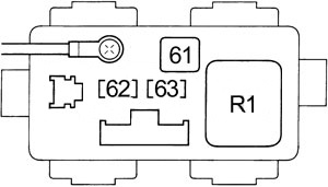
| No. | A | Circuits |
| 61 | 40 | ABS Pump Motor |
| 62 | 20 | ABS Control Unit |
| 63 | 7,5 | ABS Control Unit |
| Relay | ||
| R1 | ABS Pump Motor | |
WARNING: Terminal and harness assignments for individual connectors will vary depending on vehicle equipment level, model, and market.