Honda CR-Z (2010 – 2016) – fuse box diagram
Year of production: 2010, 2011, 2012, 2013, 2014, 2015, 2016
Passenger compartment
- Fuse Box
- Tire Pressure Monitoring System (TPMS) Control Unit
- Gauge Cotrol Module
- Immobilizer-Keyless Control Unit
- HandsFreeLink Control Unit
- Fog Light Relay (Left)
Horn Relay (Right) - Hatch Release Actuator Relay (Left)
Driver’s Door Unlock Relay (Right)
Passenger compartment fuse box
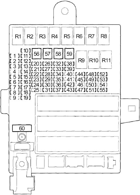
| No. | A | Circuits |
| 1 | 15 | Audio-Navigation Unit, Cargo Area Light, Data Link Connector (DLC), Driver’s Vanity Mirror Light, Passenger’s Vanity Mirror Light, Driver’s Door Courtesy Light, Passenger’s Door Courtesy Light, Left Rear Tray Light, Right Rear Tray Light, Gauge Control Module, Immobilizer-Keyless Control Unit, HandsFreeLink Control Unit, Individual Map Light, Multiplex Integrated Control Unit (MICU), Motor Control Module (MCM) |
| 2 | 7,5 | Tire Pressure Monitoring System (TPMS) Control Unit |
| 3 | 20 | Power Window Master Switch |
| 4 | — | — |
| 5 | 10 | Audio-Navigation Unit, Back-Up Light, Back-Up Light Switch (M/T), Engine Control Module (ECM (M/T)), Transmission Range Switch (CVT), Multiplex Integrated Control Unit (MICU) |
| 6 | 10 | Supplemental Restraint System (SRS) Unit |
| 7 | 10 | A/T: Powertrain Control Module – PCM (VBSOL) |
| 8 | 7,5 | Supplemental Restraint System (SRS) Unit, Occupant Detection System (ODS) Unit, Front Passenger’s Airbag Cutoff Indicator |
| 9 | 20 | Fog Light Relay, Fog Lights |
| 10 | 7,5 | A/C Compressor Clutch Relay, Blower Motor Relay, Climate Control Unit, Driver’s Seat Heater Relay, Fan Control Relay (A/C Diode B), Passenger’s Seat Heater Relay, Power Mirror Switch, Radiator Fan Relay (A/C Diode B), Rear Window Defogger Relay, Recirculation Control Motor, Seat Heater Switch Indicators |
| 11 | 7,5 | Electronic Power Steering (EPS) Control Unit, VSA Modulator-control Unit (MTR), Yaw Rateacceleration Sensor |
| 12 | 10 | Brake Pedal Position Switch (M/T), Idle Stop Switch (CVT), DCDC Converter, Evaporative Emission Control (EVAP) Canister Purge Valve, Reverse Lockout Solenoid (M/T), Mass Air Flow (MAF) Sensor, Secondary Heated Oxygen Sensor (HO2S) |
| 13 | 20 | Accessory Power Socket |
| 14 | 7,5 | Audio-Navigation Unit, Key Interlock Solenoid, HandsFreeLink Control Unit, Multiplex Integrated Control Unit (MICU) |
| 15 | 7,5 | Daytime Running Light (DRL) |
| 16 | 10 | Rear Window Wiper Motor |
| 17 | 20 | Power Window Master Switch, Passenger’s Power Window Motor (Passenger’s Power Window Switch) |
| 18 | — | — |
| 19 | — | — |
| 20 | 15 | Immobilizer-Keyless Control Unit, Engine/Powertrain Control Module (ECM/PCM) |
| 21 | 15 | Washer Motor, Multiplex Integrated Control Unit (MICU) |
| 22 | 7,5 | Electrical Load Detector (ELD), Gauge Control Module, Motor Control Module (MCM), Shift Lock Solenoid (CVT), Tire Pressure Monitoring System (TPMS) Control Unit |
| 23 | 10 | Hazard Warning Switch, Multiplex Integrated Control Unit (MICU) |
| 24 | 10 | Brake Pedal Position Switch, High Mount Brake Light, Brake Lights, Multiplex Integrated Control Unit (MICU), Engine/Powertrain Control Module (ECM/PCM), Low Horn, Horn Relay |
| 25 | 20 | Stereo Amplifier |
| 26 | 10 | Air Fuel Ratio (A/F) Sensor, Air Fuel Ratio (A/F) Sensor Relay, Fuse: No. 31 (7.5 A) |
| 27 | 20 | Power Door Lock, Multiplex Integrated Control Unit (MICU) |
| 28 | 20 | Headlamp (Main), Multiplex Integrated Control Unit (MICU) |
| 29 | 10 | Parking Light, Multiplex Integrated Control Unit (MICU) |
| 30 | 30 | Radiator Fan Motor (Radiator Fan Relay) |
| 31 | 7,5 | Engine Oil Level Sensor, A/C Condenser Fan Relay (A/C Diode A) |
| 32 | 10 | Right Headlight (Low Beam) |
| 15 | Xenon: Right HID Unit | |
| 33 | 15 | Ignition Coil Relay, Ignition Coils |
| 34 | 10 | Left Headlight (Low Beam) |
| 10 | Xenon: Left Headlight (High Beam) | |
| 35 | 7,5 | Passenger’s Door Lock Actuator |
| 36 | 10 | Driver’s Door Lock Actuator |
| 37 | 30 | VSA Modulator-Control Unit |
| 38 | — | — |
| 39 | 15 | Crankshaft Position (CKP) Sensor, Camshaft Position (CMP) Sensor, Electronic Throttle Control System (ETCS) Control Relay, Injectors, Engine/Powertrain Control Module – ECM/PCM (IGP), PGM-FI Main Relay No.1, PGM-FI Main Relay No.2 (Fuel Pump) |
| 40 | 10 | Driver’s Seat Heater, Passenger’s Seat Heater |
| 41 | — | — |
| 42 | 7,5 | Motor Control Module (MCM), MCM Relay No.1, MCM Relay No.2 |
| 43 | 7,5 | A/C Compressor (A/C Compressor Clutch Relay) |
| 44 | 7,5 | Starter Cut Relay, Powertrain Control Module – PCM (STS) |
| 45 | 7,5 | Hatch Release Actuator Relay, Hatch Release Actuator |
| 46 | — | — |
| 47 | 30 | A/C Condenser Fan Motor (A/C Condenser Fan Relay) |
| 48 | 10 | Left Headlight (High Beam) |
| 15 | Xenon: Left HID Unit | |
| 49 | 7,5 | Passenger’s Door Lock Actuator |
| 50 | — | — |
| 51 | 10 | Right Headlight (High Beam) |
| 52 | 15 | Electronic Throttle Control System (ETCS) Control Relay, Engine/Powertrain Control Module – ECM/PCM (IG1 ETCS) |
| 53 | 15 | Intelligent Power Unit (IPU) Module Fan (Motor Control Module (MCM) Relay No.2), Motor Power Inverter (MPI) Module (Motor Control Module (MCM) Relay No.2) |
| 54 | — | — |
| 55 | 10 | Left Power Mirror Defogger, Right Power Mirror Defogger |
| 56 | 30 | Front Wiper, Multiplex Integrated Control Unit (MICU) |
| 57 | 30 | Blower Motor (Blower Motor Relay) |
| 58 | 30 | VSA Modulator-Control Unit |
| 59 | 30 | Without Power Mirror Defogger: Rear Window Defogger, Extra Window Defogger, Noise Reduction Condenser |
| 40 | With Power Mirror Defogger: Rear Window Defogger, Extra Window Defogger, Noise Reduction Condenser, Fuse: No.55 (10 A)) | |
| 60 | 50 | Ignition switch |
| Relay | ||
| R1 | Power Window | |
| R2 | Blower Motor | |
| R3 | Air Fuel Ratio (A/F) Sensor | |
| R4 | Lighting No.1 | |
| R5 | Ignition Coil | |
| R6 | PGM-FI Main No.1 | |
| R7 | Electronic Throttle Control System (ETCS) Control | |
| R8 | Rear Window Defogger | |
| R9 | Lighting No.2 | |
| R10 | Starter Cut | |
| R11 | — | |
- Motor Control Module (MCM)
- Motor Control Module (MCM) Relay No.1
- Motor Control Module (MCM) Relay No.2
Engine Compartment
- Relay Box No.1
- Manual Transmission: Engine Control Module (ECM)
Automatic Transmission: Powertrain Control Module (PCM) - Relay Box No.2
- VSA Modulator-Control Unit
Engine Compartment Relay Box No.1
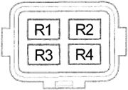
| No. | Circuits |
| R1 | A/C Compressor Clutch |
| R2 | — |
| R3 | Fan Control |
| R4 | PGM-FI Main No.2 (Fuel Pump) |
Engine Compartment Relay Box No.2
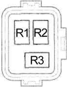
| No. | Circuits |
| R1 | A/C Condenser Fan |
| R2 | Radiator Fan |
| R3 | — |
Battery Terminal Fuse Box
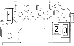
These fuses are not serviceable; replace the battery terminal fuse box as an assembly.
| No. | A | Circuits |
| 1 | 100 | DC-DC Converter, Lighting Relay No.1, Lighting Relay No.2, Power Window Relay, Fuses: No. 1, 2, 3, 9, 17, 25, 26, 27, 28, 29, 30, 32, 33, 34, 37, 39, 40, 42, 43, 45, 47, 48, 51, 52, 53, 57, 58, 59, 60 |
| 2 | 70 | Electronic Power Steering (EPS) Control Unit |
| 3 | 20 | Fuses: 23, 24 |
WARNING: Terminal and harness assignments for individual connectors will vary depending on vehicle equipment level, model, and market.