Honda Fit (2006 – 2008) – fuse box diagram
Year of production: 2006, 2007, 2008
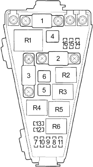
Passenger Compartment
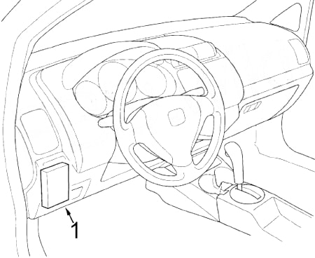
- Fuse Box
Passenger Compartment Fuse Box
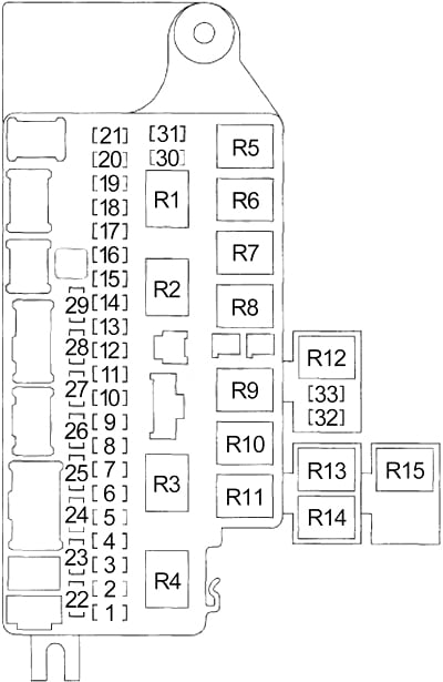
| No. |
A |
Circuit |
| 1 | 10 | Back-up Lights, A/T Reverse Relay |
| 2 | – | – |
| 3 | 10 | Gauge Control Module, Keyless Receiver Unit, Security Control Unit, Electronic Power Steering (EPS) Control Unit, Imoes Unit, Tire Pressure Monitoring System (TPMS) Control Unit Control Unit |
| 4 | 10 | Gauge Control Module (Turn Signal/Hazard Circuit) |
| 5 | – | – |
| 6 | 30 | Windshield Wiper Motor, Windshield Washer Motor, Rear Window Washer Motor |
| 7 | 10 | Occupant Detection System (ODS) Unit, Supplemental Restraint System (SRS) Unit |
| 8 | 7.5 | Daytime Running Lights Control Unit |
| 9 | 20 | Rear Window Defogger |
| 10 | 7.5 | Left Mirror, Right Mirror, Rear Window Defogger Switch Indicator Light, Rear Window Defogger Relay, Blower Motor Relay, Radiator Fan Relay, A/C Compressor Clutch Relay, A/C Condenser Fan Relay |
| 11 | 15 | ECM/PCM, Immobilizer Control Unit-Receiver, Fuel Pump |
| 12 | 10 | Power Window Relay, Power Window Master Switch, Rear Window Wiper Motor |
| 13 | 10 | Supplemental Restraint System (SRS) Unit |
| 14 | 15 | PGM-FI Main Relay No.1, PGM-FI Main Relay No.2, ECM/PCM |
| 15 | 20 | Left Rear Window Motor |
| 16 | 20 | Right Rear Window Motor |
| 17 | 20 | Front Passenger’s Window Motor |
| 18 | 10 | Daytime Running Lights Control Unit |
| 7.5 | Tire Pressure Monitoring System (TPMS) Control Unit | |
| 19 | – | – |
| 20 | – | – |
| 21 | 20 | Fog Lights |
| 22 | 10 | Taillight Relay, Illumination Lights, Left Front Side Marker/Parking Light, Right Front Side Marker/Parking Light, Left Taillight, Right Taillight, License Plate Light, Left Rear Side Marker Light/Taillight, Right Rear Side Marker Light/Taillight |
| 23 | 10 | Air Fuel Ratio (A/F) Sensor, Evaporative Emission Control (EVAP) Canister Vent Shut Valve |
| 24 | – | – |
| 25 | 7.5 | ABS Modulator-Control Unit |
| 26 | 7.5 | Audio Unit, Gauge Control Module, Key Interlock Solenoid |
| 27 | 15 | Accessory Power Socket |
| 28 | 20 | Driver’s Door Lock Actuator, Front Passenger’s Door Lock Actuator, Left Rear Door Lock Actuator, Right Rear Door Lock Actuator, Tailgate Lock Actuator |
| 29 | 20 | Driver’s Window Motor, Power Window Master Switch |
| 30 | – | – |
| 31 | 7.5 | Air Fuel Ratio (A/F) Sensor Relay |
| 32 | 15 | Throttle Actuator Control Module |
| 33 | 15 | Ignition Coil Relay |
| Relay | ||
| R1 | Starter Cut | |
| R2 | Power Window | |
| R3 | Blower Motor | |
| R4 | A/T Reverse | |
| R5 | Door Lock | |
| R6 | Driver’s Door Unlock | |
| R7 | Passenger’s Door Unlock / Tailgate Unlock | |
| R8 | Taillight | |
| R9 | Ignition Coil | |
| R10 | PGM-FI Main No.2 (Fuel Pump) | |
| R11 | PGM-FI Main No.1 | |
| R12 | Throttle Actuator Control Module | |
| R13 | Rear Window Defogger | |
| R14 | Air Fuel Ratio (A/F) Sensor | |
| R15 | Fog Light | |
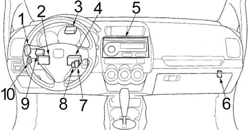
- Security Control Unit
- Electronic Power Steering (EPS) Control Unit
- Tire Pressure Monitoring System (TPMS) Control Unit
- Daytime Running Lights Control Unit
- Audio Unit
- Throttle Actuator Control Module
- Low Beam Cut Relay
- Daytime Running Lights Relay
- Imoes Unit
- Keyless Receiver Unit
Engine Compartment
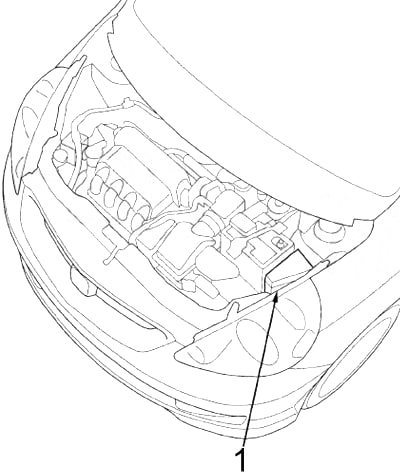
- Fuse Box
Engine Compartment Fuse Box No.1
| No. |
A |
Protected Component |
| 1 | 80 | Battery, Power Distribution |
| 2 | 60 | Electronic Power Steering (EPS) Control Unit |
| 3 | 50 | Ignition Switch |
| 4 | 30 | ABS Modulator-Control Unit |
| 5 | 40 | Blower Motor |
| 6 | 40 | Fuses: No. 14, 15, 16, 17, 28, 29 |
| 7 | 30 | Fuses: No. 18, 21 |
| 8 | 10 | Keyless Receiver Unit, Gauge Control Module, Security Control Unit, Immobilizer Control Unit-Receiver, Audio Unit, Imoes Unit |
| 9 | 30 | Fuses: No. 22, 23 |
| 10 | 30 | Radiator Fan Motor |
| 11 | 30 | A/C Condenser Fan Motor, A/C Compressor Clutch |
| 12 | 20 | Right Headlight |
| 13 | 20 | Left Headlight, High Beam Indicator |
| 14 | 10 | Gauge Control Module (Turn Signal/Hazard Circuit) |
| 15 | 30 | ABS Modulator-Control Unit |
| 16 | 15 | Horn Relay, Horn, ECM/PCM, Brake Lights, High Mount Brake Light |
| Relay | ||
| R1 | Electrical Load Detector (ELD) | |
| R2 | Radiator Fan | |
| R3 | Horn | |
| R4 | Headlight | |
| R5 | A/C Condenser Fan | |
| R6 | A/C Compressor Clutch | |
WARNING: Terminal and harness assignments for individual connectors will vary depending on vehicle equipment level, model, and market.