Honda Insight (2000 – 2006) – fuse box diagram
Year of production: 2000, 2001, 2002, 2003, 2004, 2005, 2006
Passenger compartment
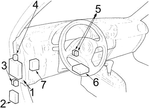
- Fuse Box
- Daytime Running Lights (DRL) Control Unit
- Daytime Running Lights (DRL) Relay
Low Beam Cut Relay - ’02-’06: Air Fuel (A/F) Ratio Sensor Relay
- PGM-FI Main Relay
Reverse Relay - Supplemental Restraint System (SRS) Unit
- Keyless Door Lock Control Unit
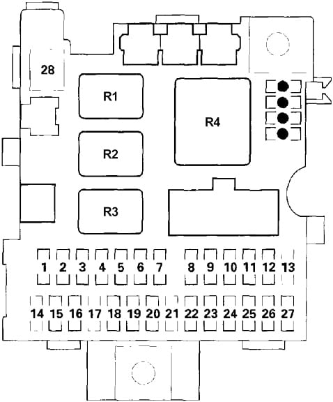
Passenger compartment fuse box
| No. | A | Circuits |
| 1 | 10 | Supplemental Restraint System (SRS) Unit |
| 2 | 15 | F3u20el Pump, Supplemental Restraint System (SRS) Unit |
| 3 | 20 | Windshield Washer Motor, Windshield Wiper Motor, Windshield Wiper Intermittent Relay |
| 4 | 7,5 | DC-DC Converter, Electrical Load Detector (ELD) Unit, Evaporative Emission Control (EVAP) Canister Vent Shut Valve, EVAP Purge Control Solenoid Valve, Secondary Heated Oxygen Sensor (HO2S), Vehicle Speed Sensor (VSS), Transmission Control Module (TCM) |
| 5 | 7,5 | Turn Signal Lights, Turn Signal/Hazard Relay |
| 6 | 7,5 | Electronic Power Steering (EPS) Control Unit, Gauge Assembly, Keyless Door Lock Control Unit, Power Window Control Unit (Power Window Master Switch), Power Window Relay, Shift Lock Solenoid |
| 7 | 15 | Ignition Coils |
| 8 | 20 | Passenger’s Power Window Motor |
| 9 | 7,5 | Engine Control Module (ECM), Starter Cut Relay |
| 10 | 20 | Power Window Control Unit (Power Window Master Switch), Driver’s Power Window Motor |
| 11 | 7,5 | Audio Unit |
| 12 | 10 | Accessory Power Socket |
| 13 | — | — |
| 14 | 20 | ’02-’06: Air Fuel (A/F) Ratio Sensor, Engine Control Module (ECM) (Air Fuel (A/F) Ratio Sensor Relay) |
| 15 | 10 | Audio Unit, Climate Control Unit/Heater Control Panel Lights, Dash Lights, Gauge Lights, Front Parking Lights, Front Side Marker Lights, License Plate Light, Taillights |
| 16 | 7,5 | ABS Modulator-Control Unit, A/C Compressor Clutch Relay, Blower Motor Relay. Blower Motor High Relay, Climate Control Unit/Heater Control Panel, A/C Condenser Fan Relay, Fan Control Relay, Mode Control Motor, Radiator Fan Relay, Rear Window Defogger Relay, Recirculation Control Motor |
| 17 | 7,5 | Daytime Running Lights (DRL) Control Unit |
| 18 | 7,5 | Battery Condition Monitor (BCM) Module, Climate Control Unit/Heater Control Panel, Data Link Connector (DLC), Engine Control Module (ECM), Gauge Assembly, Motor Control Module (MCM) |
| 19 | 7,5 | Cargo Area Light, Ceiling Light/Spotlights |
| 20 | 10 | Audio Unit |
| 21 | 10 | Daytime Running Lights (DRL) Control Unit |
| 22 | 20 | Keyless Door Lock Control Unit |
| 23 | 7,5 | Hatch Opener Relay, Hatch Opener Actuator |
| 24 | 7,5 | Battery Module Fan, High Speed Battery Module Fan Control Relay, Ignition Hold Relay, Low Speed Battery Module Fan Control Relay, Motor Control Module (MCM) |
| 25 | — | — |
| 26 | 10 | Rear Window Washer Motor, Rear Window Wiper Motor |
| 27 | 7,5 | Back-Up Lights, Reverse Relay (CVT) |
| 28 | — | — |
| Relay | ||
| R1 | Taillight | |
| R2 | Starter Cut | |
| R3 | Power Window | |
| R4 | Turn Signal/Hazard | |
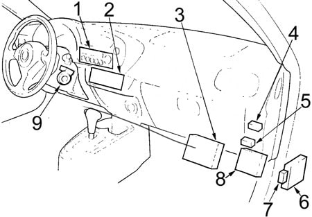
- Climate Control Unit or Heater Control Panel
- Audio Unit
- Engine Control Module (ECM)
- Blower Motor High Relay
- CVT: Electronic Power Steering (EPS) Motor Relay
- M/T: Electronic Power Steering (EPS) Control Unit
CVT: Transmission Control Module (TCM) - M/T: Electronic Power Steering (EPS) Motor Relay
- CVT: Electronic Power Steering (EPS) Control Unit
- Immobilizer Receiver Unit
Engine Compartment
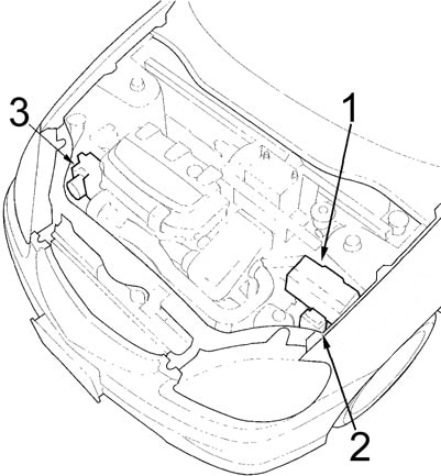
- Fuse Box
- Relay Box
- ABS Modulator-Control Unit
Engine Compartment Fuse box
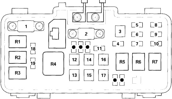
| No. | A | Circuits |
| 1 | 50 | Ignition Switch (BAT) |
| 2 | 80 | Battery, Power Distribution |
| 3 | 30 | ABS Modulator-Control Unit |
| 4 | 10 | Turn Signal/Hazard Relay, Turn Signal Lights |
| 5 | 15 | Low Speed Motor Power Inverter (MPI) Module Fan Control Relay, High Speed Motor Power Inverter Module (MPI) Fan Control Relay, PDU Fan Motor |
| 6 | 10 | ABS Modulator-control Unit, Engine Control Module (ECM), High Mount Brake Light, Taillights |
| 7 | 15 | PGM-FI Main Relay (IGP), Key Interlock Solenoid (CVT) |
| 8 | 15 | Left Headlight, High Beam Indicator Light, Daytime Running Lights Control Unit |
| 9 | — | — |
| 10 | 15 | Right Headlight, Daytime Running Lights Control Unit |
| 11 | 30 | Radiator Fan Motor |
| 12 | 40 | Blower Motor |
| 13 | 30 | Rear Window Defogger, Noise Condenser |
| 14 | 20 | ABS Modulator-Control Unit |
| 15 | 40 | Electronic Power Steering (EPS) Control Unit |
| 16 | 30 | Taillight Relay, Fuse (Passenger Compartment Fuse Box): No. 14, 18, 19, 20, 21, 22, 23 |
| 17 | 40 | Power Window Relay, Fuse (Passenger Compartment Fuse Box): No. 8, 10 |
| 18 | 7,5 | Battery Condition Monitor (BCM) Module, High Voltage Contactor, Motor Control Module (MCM), Voltage Converter Module |
| 19 | 20 | A/C Condenser Fan Motor, A/C Compressor Clutch |
| Relay | ||
| R1 | A/C Compressor Clutch | |
| R2 | Radiator Fan | |
| R3 | A/C Condenser Fan | |
| R4 | Blower Motor | |
| R5 | Horn | |
| R6 | Headlight No.2 | |
| R7 | Headlight No.1 | |
Engine Compartment Relay Box
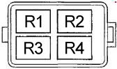
| No. | Circuits |
| R1 | Rear Window Defogger |
| R2 | PGM-FI Main No.2 (Fuel Pump) |
| R3 | Fan Control |
| R4 | Windshield Wiper Intermittent |
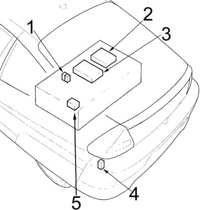
- High Speed Battery Module Fan Control Relay
Low Speed Battery Module Fan Control Relay - Motor Control Module (MCM)
- Battery Condition Monitor (BCM) Module
- Hatch Opener Relay
- Relay Box
Luggage Compartment Relay Box
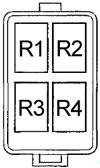
| No. | Circuits |
| R1 | High Voltage Contactor Control Relay |
| R2 | Low Speed Motor Power Inverter (MPI) Module Fan Control Relay |
| R3 | High Speed Motor Power Inverter (MPI) Module Fan Control Relay |
| R4 | Ignition Hold |
WARNING: Terminal and harness assignments for individual connectors will vary depending on vehicle equipment level, model, and market.