Honda Passport (1998 – 2002) – fuse box diagram
Year of production: 1998, 1999, 2000, 2001, 2002
Passenger Compartment Fuse Box
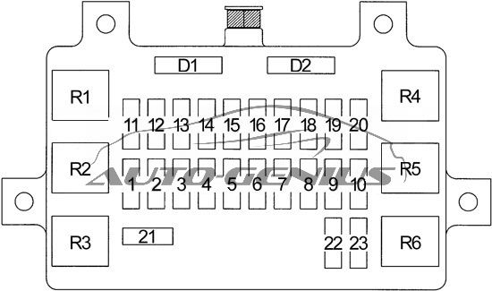
| No. | A | Circuits |
| 1 | 20 | Accessory Power Sockets |
| 2 | 15 | Clock, Stereo Sound System |
| 3 | 10 | Starting System |
| 4 | 15 | Taillight Relay (A/T Gear Position Indicator, Alarm and Relay Controls, Dash and Console Lights, Fuel Injection System, Headlight Switch, Lights-on Reminder, Multiplex Control System, Parking Light, Tail Light, License Light, Power Door Locks/Keyless Entry/Security System, Trailer Lights Connector) |
| 5 | 10 | Alarm and Relay Controls, Cargo Light, Ceiling Light, Courtesy Lights, Dome Light Relay (’01), Ignition Key Reminder (LX), Map Light |
| 6 | 15 | ABS, Automatic Transmission Controls, Brake Lights, Cruise Control, Interlock System, Trailer Lighting Connector |
| 7 | 20 | Ignition Key Reminder (EX), Power Door Locks/Keyless Entry/Security System |
| 8 | 10 | Power Mirror Defoggers |
| 9 | 15 | Rear Window Defogger |
| 10 | 15 | Rear Window Defogger |
| 11 | 15 | ABS, Gauges, Indicators, Interlock System, Multiplex Control System |
| 12 | 15 | Automatic Transmission Controls, Fuel Injection System, Starting System |
| 13 | 15 | Ignition System |
| 14 | 15 | Automatic Transmission Controls, Back-up Lights, Cruise Control, Map Light Timer (’01), Multiplex Control System, Shift-on-the-fly System (’01-’02), Transmission Range Switch |
| 15 | 15 | Alarm and Relay Control Unit, Blower Controls, Power Moonroof, Power Windows, Shift-on-the-fly System (’00), Trailer Lighting Connector, Turn Signal Lights |
| 16 | 10 | Alarm and Relay Control Unit, Rear Window and Mirror Defoggers, Rear Wiper/Washer |
| 17 | 20 | Alarm and Relay Control Unit, Windshield Wiper/Washer |
| 18 | 10 | Power Mirrors, Stereo Sound System |
| 19 | 15 | Accessory Power Sockets, Cigarette Lighter |
| 20 | 10 | Security and Keyless Entry System |
| 21 | 30 | Power Moonroof, Power Seat (’01-’02), Power Windows |
| 22 | 10 | SRS |
| 23 | — | — |
| Relay | ||
| R1 | — | Taillight |
| R2 | — | — |
| R3 | — | Accessory Power Socket |
| R4 | — | Power Window |
| R5 | — | ’01: Dome Light |
| R6 | — | Rear Window Defogger |
| Diode | ||
| D1 | — | Ceiling Lights, Keyless Entry and Security System |
| D2 | — | Keyless Entry and Security System |
Engine Compartment Fuse Box (Type 1)
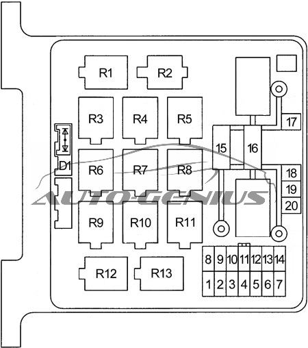
| No. | A | Circuits |
| 1 | 15 | Hazard Warning Lights, Trailer Lighting Connector |
| 2 | 10 | Alarm and Relay Control Unit, Data Link Connector (DLC), Security Horn |
| 3 | 10 | Alternator |
| 4 | — | — |
| 5 | 15 | Blower Controls |
| 6 | 15 | Blower Controls |
| 7 | 10 | Air Delivery |
| 8 | 10 | Left Headlights, Fog Lights |
| 9 | 10 | Right Headlight |
| 10 | 15 | Fog Lights |
| 11 | 20 | Heated Oxygen Sensors |
| 12 | 20 | Fuel Pump |
| 13 | 15 | Automatic Transmission Controls, Fuel Injection System, Gauges |
| 14 | Daytime Running Lights | |
| 15 | 60 | Fuel Injection System, Power Distribution (BAT) |
| 16 | 100 | A/C Compressor Controls, Blower Controls, Charging System, Fog Lights, Power Distribution (BAT), Starting System |
| 17 | 30 | Engine Control Module |
| 18 | 50 | ABS |
| 19 | 50 | Power Distribution (BAT) |
| 20 | 30 | Condenser Fan |
| Relay | ||
| R1 | — | Fuel Pump |
| R2 | — | — |
| R3 | — | Headlight |
| R4 | — | Starter |
| R5 | — | Condenser Fan |
| R6 | — | — |
| R7 | — | — |
| R8 | — | A/C Thermo |
| R9 | — | Engine Control Module (ECM) (M/T) |
| — | Powertrain Control Module (PCM) (A/T) | |
| R10 | — | — |
| R11 | — | Fog Light |
| R12 | — | Heater-A/C |
| R13 | — | A/C Compressor |
| Diode | ||
| D1 | — | Brake System Indicator Light |
Engine Compartment Fuse Box (Type 2)
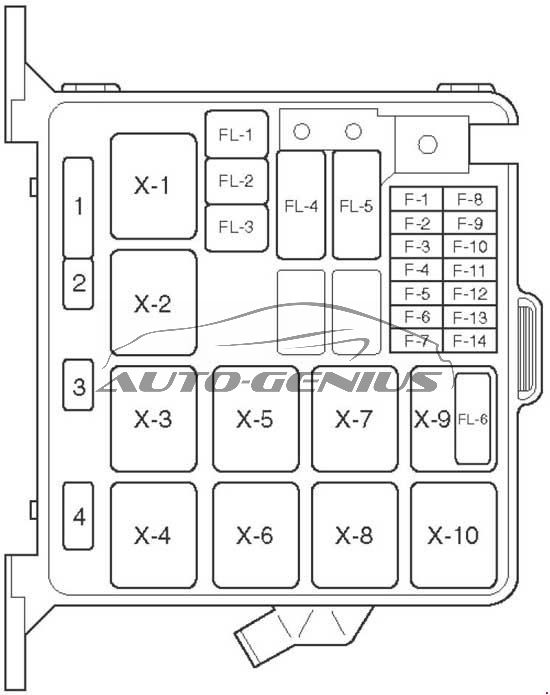
| No. | A | Circuits |
| F-1 | 15 | Hazard warning light |
| F-2 | 10 | Alarm & relay control unit, Horn, Anti – theft horn |
| F-4 | 20 | Blower motor, Blower resistor |
| F-5 | 10 | A/C thermostat relay, Electronic thermostat, A/C compressor relay, Magnetic clutch |
| F-6 | — | — |
| F-7 | — | — |
| F-8 | 10 | Headlight – LH, High beam indicator light, Fog light relay |
| F-9 | 10 | Headlight – RH |
| F-10 | 15 | Fog light |
| F-11 | 20 | Oxygen sensor |
| F-12 | 20 | Fuel pump |
| F-13 | 15 | Engine control module |
| F-14 | — | — |
| FL1 | 60 | EHCU |
| FL2 | 30 | Condenser fan unit |
| FL3 | — | — |
| FL4 | 100 | Ignition switch, starter relay, A/C, generator, heater relay, Fuse: F10, FL1, FL2, FL5, FL6 |
| FL:5 | 60 | Ignition switch, fuel pump relay, engine control module relay, power train module |
| FL6 | — | — |
| Relay | ||
| X1 | — | Headlight |
| X2 | — | Fog light |
| X3 | — | Starter |
| X4 | — | A/C compressor |
| X5 | — | Thermo |
| X6 | — | Heater |
| X7 | — | Fuel pump |
| X8 | — | Engine control module |
| X9 | — | 6VD1: Condenser fan |
| X10 | — | — |
| Diode | ||
| 1 | — | Brake |
| 2 | — | — |
| 3 | — | — |
| 4 | — | — |
WARNING: Terminal and harness assignments for individual connectors will vary depending on vehicle equipment level, model, and market.