Hummer H2 (2003 – 2007) – fuse box diagram
Year of production: 2003, 2004, 2005, 2006, 2007
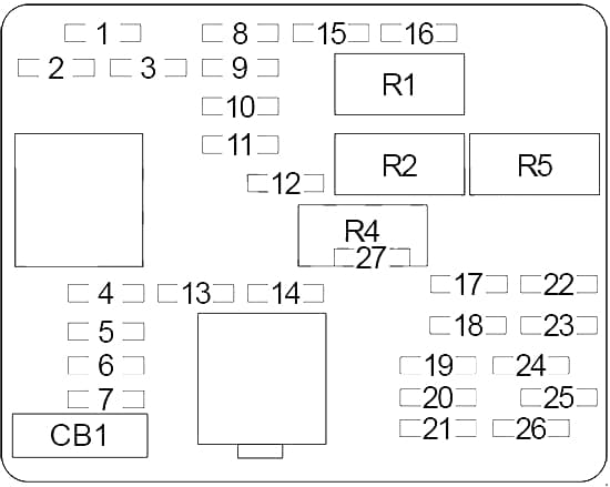
Passenger compartment fuse box
| No. |
A |
Protected Component |
| 1 | 15 | Rear Window Wiper/Washer Switch |
| 2 | 10 | Rear Heated Seats Modules |
| 3 | 15 | Transfer Case Shift Control Switch (Four Wheel Drive Switch), Electronically Controlled Air Suspension Switch/Module, Ride Height Switch |
| 4 | 10 | Brake Transmission Shift Interlock, Powertrain Control Module, Transmission |
| 5 | 15 | Stoplamps, Brake Module, Electronic Throttle Control Module, Turn Signal/Hazard Flasher Module, Fuse: “14” |
| 6 | 15 | Driver Door Module |
| 7 | 10 | Liftgate Door Lock Relay |
| 8 | 10 | Body Builder Provision |
| 9 | 30 | – |
| 10 | 10 | Inside Rearview Mirror, Climate Control System (HVAC Control Module and Actuators) |
| 11 | 10 | Cruise Control |
| 12 | 10 | Stop Lamp Switch |
| 13 | 10 | Body Control Module (BCM) |
| 14 | 10 | Vehicle and Trailer Center High Mounted Stop Lamp |
| 15 | 25 | Windshield Wipers |
| 16 | 10 | Body Control Module (BCM) |
| 17 | 10 | Left Turn Signal/Stop Trailer |
| 18 | 10 | Right Turn Signal/Stop Trailer |
| 19 | 20 | Instrument Panel and Rear Cargo Area Power Outlets |
| 20 | 15 | Body Control Module (BCM) |
| 21 | 15 | Body Control Module (BCM) |
| 22 | 10 | Left Turn Signals and Side Markers Lamps, Instrument Panel Cluster |
| 23 | 10 | Right Turn Signals and Side Markers Lamps, Instrument Panel Cluster |
| 24 | 20 | Door Lock/Unlock Relay |
| 25 | 25 | Turn Signal/Hazard Flasher Module |
| 26 | 15 | Body Control Module (BCM) |
| 27 | 10 | Passenger Door Module |
| Circuit Breaker | ||
| CB1 | 25 | Left Rear Power Window Circuit Breaker and Driver Door Module |
| Relay | ||
| R1 | Power Door Lock | |
| R2 | Power Door Unlock | |
| R3 | – | |
| R4 | – | |
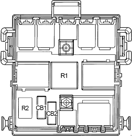
Passenger compartment relay box
| No. |
A |
Circuit Breaker |
| CB1 | 30 | Driver and Passenger Seat Module |
| CB2 | 25 | Right Rear Power Window, Passenger Door Module |
| Relay | ||
| R1 | Rear Window Defogger | |
| R2 | – | |
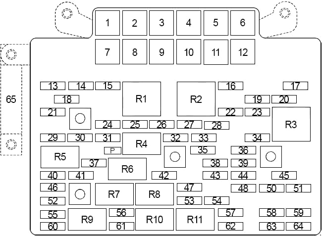
Engine compartment fuse box
| No. |
A |
Protected Component |
| 1 | 40 | Accessory Power/Trailer Wiring |
| 2 | – | – |
| 3 | 50 | Circuit Breaker (Passenger Compartment Relay Box): “CB1”, “CB2” |
| 4 | 40 | Blower Motor (High Speed) |
| 5 | 50 | Fuse (Passenger Compartment): “6”, “19”, “24” “27” |
| 6 | 30 | Off Road Lamps, Trailer Wiring |
| 7 | 60 | ABS |
| 8 | 60 | Electronically Controlled Air Suspension Relay |
| 9 | 40 | Ignition Switch |
| 10 | – | – |
| 11 | 40 | Ignition Switch |
| 12 | 50 | Fuse (Passenger Compartment): “20”, “25” “26”, “CB1” |
| 13 | 15 | Parking Lamps Trailer Wiring |
| 14 | 10 | Right Rear Parking and Side Marker Lamps, License Lamp |
| 15 | 10 | Left Rear Parking and Side Marker Lamps, License Lamp |
| 16 | 10 | Roof Marker Lamps, SIR Defeat Switch, Clearance Lamps, Marker Lamps, Trailer Jumper |
| 17 | 25 | Stop Lamp Switch |
| 18 | 10 | Body Control Module (BCM) |
| 19 | 25 | Sunroof |
| 20 | 30 | Electronic Brake Control Module, Off-Road Lamps |
| 21 | 15 | EVAP Canister Vent Solenoid |
| 22 | 30 | Rear HVAC Module |
| 23 | 20 | Auxiliary Power Outlet – Console |
| 24 | 15 | Powertrain Control Module (PCM), Evaporative Emission (EVAP) Canister Purge Solenoid, Mass Air Flow (MAF) Sensor, Intake Air Temperature (IAT) Sensor |
| 25 | 15 | Throttle Actuator Control (TAC), Electronic Brake Controller |
| 26 | 15 | Ignition Coils, Fuel Injectors |
| 27 | 15 | Ignition Coils, Fuel Injectors |
| 28 | 10 | Instrument Panel Cluster, Air Conditioning Relay, Turn Signal/Hazard Switch, Starter Relay, Electronic Brake Controller TC2 Mode Switch |
| 29 | 30 | Electronic Brake Controller |
| 30 | 10 | Backup Lamps Trailer Wiring |
| 31 | 20 | Powertrain Control Module, Fuel Pump |
| 32 | 15 | Oxygen Sensors |
| 33 | 20 | Backup Lamps, Park/Neutral Position Switch (PNP) |
| 34 | 30 | Rear Window Defogger Relay |
| 35 | 15 | Oxygen Sensors |
| 36 | 15 | Inflatable Restraint Instrument Panel Module Disable Switch, Inflatable Restraint Sensing and Diagnostic Module |
| 37 | 10 | Front Parking Lamps, Front Side Marker Lamps |
| 38 | 10 | Rear Window Defogger Relay |
| 39 | 10 | Body Control Module (BCM) |
| 40 | 10 | Left Headlamp (High Beam) |
| 41 | – | – |
| 42 | 10 | Daytime Running Light Relay |
| 43 | 10 | Instrument Panel Cluster/Driver Information Center |
| 44 | 10 | Climate Control Controller/ Electronically Controlled Air Suspension Module |
| 45 | 15 | Cigarette Lighter, Data Link Connector |
| 46 | 10 | Right Headlamp (High Beam) |
| 47 | 10 | Air Conditioning Compressor Relay |
| 48 | 25 | Rear Wiper/Washer |
| 49 | – | – |
| 50 | 15 | Audio System, Rear Seat Audio |
| 51 | 15 | Rear Heated Seats, HomeLink (Garage Door Opener) |
| 52 | 10 | Left Headlamp (Low Beam) |
| 53 | 10 | Brake Transmission Shift Interlock System |
| 54 | 10 | Starting System, Ignition Switch, Powertrain Control Module (PCM) |
| 55 | 10 | Right Headlamp (Low Beam) |
| 56 | – | – |
| 57 | 15 | Windshield and Rear Window Washer Pump |
| 58 | 15 | Vehicle Communication Interface Module (VCIM) |
| 59 | 30 | Radio Amplifier |
| 60 | – | – |
| 61 | 15 | Horn |
| 62 | – | – |
| 63 | 30 | Transfer Case Control Module (All-Wheel Drive Module) |
| 64 | – | – |
| 65 | 125 | Cust Feed |
| Relay | ||
| R1 | Parking Lamps, Side Marker Lamps | |
| R2 | Starter | |
| R3 | Ignition | |
| R4 | Fuel Pump | |
| R5 | Headlamp High Beam | |
| R6 | Daytime Running Light | |
| R7 | Headlamp (Low Beam) | |
| R8 | Air Conditioning Compressor | |
| R9 | – | |
| R10 | Horn | |
| R11 | Windshield and Rear Window Washer Pump | |
WARNING: Terminal and harness assignments for individual connectors will vary depending on vehicle equipment level, model, and market.