Hummer H2 (2008 – 2009) – fuse box diagram
Year of production: 2008, 2009
Passenger compartment fuse box
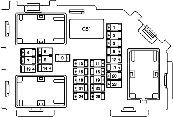
| No. |
A |
Protected Component |
| 1 | 20 | Heated Rear Seat Control Module |
| 2 | 20 | Rear Cargo Accessory Power Outlets |
| 3 | 2 | Steering Wheel Controls Backlight |
| 4 | 15 | Driver Door Module |
| 5 | 15 | Dome Lamps, Front Passenger Side Turn Signal, Body Control Module (BCM) |
| 6 | 15 | Driver Side Turn Signal and Stop Lamp, Body Control Module (BCM) |
| 7 | 10 | Instrument Panel Back Lighting, Body Control Module (BCM) |
| 8 | 15 | Passenger Side Turn Signal |
| 9 | 10 | Passenger Door Module |
| 10 | 15 | Power Door Lock 2 (Unlock Feature) |
| 11 | 15 | Power Door Lock 2 (Lock Feature) |
| 12 | 15 | Stop Lamps, Center-High Mounted Stoplamp, Body Control Module (BCM) |
| 13 | 30 | Rear Climate Controls |
| 14 | – | – |
| 15 | 15 | Body Control Module (BCM) |
| 16 | 20 | Floor Console Power Outlets |
| 17 | 10 | Interior Lamps, Body Control Module (BCM) |
| 18 | 15 | Power Door Lock 1 (Unlock Feature) |
| 19 | 5 | Infotainment System (Video Display), Remote Keyless Entry System |
| 20 | 10 | Universal Home Remote System (Garage Door Opener) |
| 21 | 15 | Power Door Lock 1 (Lock Feature) |
| 22 | 10 | Vehicle Communication Interface Module (OnStar®) |
| 23 | 25 | Rear Window Wiper Motor |
| 24 | – | – |
| 25 | 10 | Driver Seat Module |
| Circuit Breaker | ||
| CB1 | 25 | Driver Side Power Window |
| Relay (Non-Serviceable) | ||
| R1 | Power Door Lock | |
Passenger compartment relay box
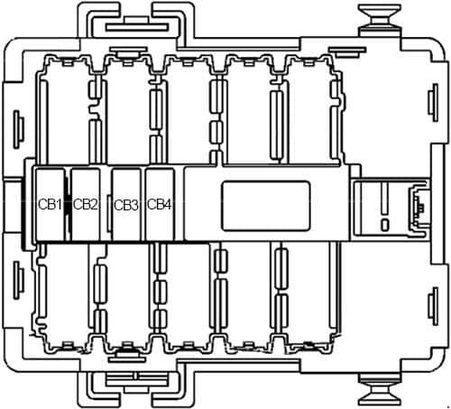
| No. |
A |
Circuit Breaker |
| CB1 | 25 | Passenger Side Power Window |
| CB2 | 25 | Passenger Seat |
| CB3 | 25 | Driver Seat |
| CB4 | 25 | Rear Sliding Window |
| Relay (Non-Serviceable) | ||
| R1 | Multifunction Switch (PARK ENABLE PCB) | |
Engine compartment fuse box
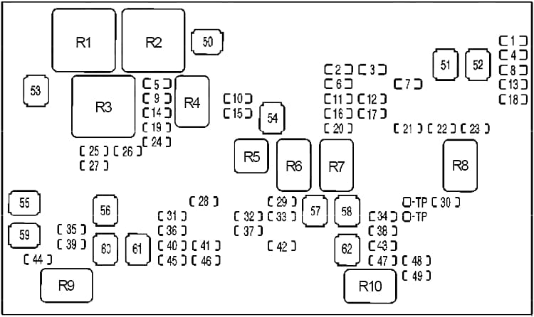
| No. |
A |
Protected Component |
| 1 | 10 | Left Trailer Stop/Turn Lamp |
| 2 | 15 | Air Temperature (IAT) Sensor, Evaporative Emission (EVAP) Canister Purge Solenoid Valve |
| 3 | 15 | Engine Control Module (ECM) |
| 4 | 10 | Right Trailer Stop/Turn Lamp |
| 5 | 15 | Washer Fluid Pump (Front) |
| 6 | 10 | Oxygen Sensors |
| 7 | 30 | Vehicle Stability System, Antilock Brake System |
| 8 | 10 | Trailer Back-Up Lamps |
| 9 | 10 | Left Headlamp (Low Beam) |
| 10 | 10 | Engine Control Module (ECM) |
| 11 | 20 | Fuel Injectors, Ignition Coils (Right Side) |
| 12 | 15 | Transmission Control Module, Evaporative Emission (EVAP) Canister Vent Solenoid Valve |
| 13 | 10 | Back-Up Lamps |
| 14 | 10 | Right Headlamp (Low Beam) |
| 15 | 10 | Air Conditioning Compressor Clutch |
| 16 | 10 | Oxygen Sensors |
| 17 | 15 | Transmission Controls (Ignition) |
| 18 | 20 | Fuel Pump, Engine Control Module (ECM) |
| 19 | 15 | Washer Fluid Pump (Rear) |
| 20 | 20 | Fuel Injectors, Ignition Coils (Left Side) |
| 21 | 15 | Trailer Park Lamps |
| 22 | 15 | Left Park Lamps |
| 23 | 15 | Right Park Lamps |
| 24 | 15 | Horn |
| 25 | 10 | Right Headlamp (High Beam) |
| 26 | 10 | Daytime Running Lamps (DRL) |
| 27 | 10 | Left Headlamp (High Beam) |
| 28 | 30 | Sunroof |
| 29 | 2 | Key Ignition System, Theft Deterrent System |
| 30 | 25 | Windshield Wiper |
| 31 | 30 | Upfitter Provision |
| 32 | 15 | Electrically Controlled Air Suspension |
| 33 | 10 | Climate Controls (HVAC) |
| 34 | 10 | Airbag System |
| 35 | 30 | Audio Amplifier |
| 36 | 15 | Audio System, Rear Seat Audio Controller, Digital Radio Receiver |
| 37 | 10 | Miscellaneous, Cruise Control, Rear Vision Camera |
| 38 | 15 | Airbag System |
| 39 | 10 | Instrument Panel Cluster, Body Control Module (BCM) |
| 40 | 10 | Run, Accessory, Midgate Module |
| 41 | 10 | Auxiliary Climate Control |
| 42 | 30 | Rear Window Defogger (SUV), Midgate Control Module (SUT) |
| 43 | 15 | Upfitter Provision |
| 44 | 15 | Cigarette Lighter, Auxiliary Power Outlet, Data Link Connector |
| 45 | 10 | Upfitter Provision, Special Equipment Option (SEO) |
| 46 | 10 | Climate Controls |
| 47 | 15 | Engine Control Module (ECM), Fuel System Control Module, Electronic Brake Control Module |
| 50 | 40 | Cooling Fan (Low Speed) Relay |
| 51 | 60 | Electronically Controlled Air Suspension Relay |
| 52 | 60 | Vehicle Stability System, Antilock Brake System |
| 53 | 40 | Cooling Fan (High Speed) Relay |
| 54 | 40 | Starter Relay |
| 55 | 30 | Trailer Brake Module |
| 56 | 60 | Left Bussed Electrical Center |
| 57 | 60 | Heated Windshield Washer System |
| 58 | 30 | Four-Wheel Drive System |
| 59 | 40 | Trailer Connector Battery Power |
| 60 | 60 | Mid Bussed Electrical Center 1 |
| 61 | 40 | Climate Control Blower |
| 62 | 60 | Left Bussed Electrical Center 2 |
| Relay | ||
| R1 | Cooling Fan (High Speed) | |
| R2 | Cooling Fan (Low Speed) | |
| R3 | Cooling Fan Control | |
| R4 | Headlamp (Low Beam) | |
| R5 | Air Conditioning Compressor | |
| R6 | Starter | |
| R7 | Powertrain Control Module | |
| R8 | Parking Lamps | |
| R9 | Rear Window Defogger | |
| R10 | Switched Power | |
| Non-Serviceable | ||
| R11 | Back-Up Lamps | |
| R12 | Daytime Running Lamps | |
| R13 | Cooling Fan (Right) | |
| R14 | Cooling Fan (Right), Cooling Fan Control | |
| R15 | Cooling Fan (Left) | |
| R16 | Washer Fluid Pump (Front) | |
| R17 | Headlamp (High Beam) | |
| R18 | Horn | |
| R19 | Liftgate Release | |
| R20 | Washer Fluid Pump (Rear) | |
| R21 | “FWD”, “HTR STR/WHL” | |
| R22 | Left Trailer Stop Lamp | |
| R23 | Right Trailer Stop Lamp | |
| R24 | Wiper | |
| R25 | Windshield Wiper Motor | |
WARNING: Terminal and harness assignments for individual connectors will vary depending on vehicle equipment level, model, and market.