Infiniti Q60 (2013 – 2015) – fuse box diagram
Year of production: 2013, 2014, 2015
Passenger Compartment Fuse Box
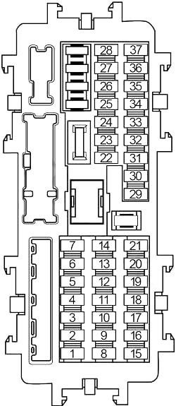
| No. | A |
Circuit Protected |
| 1 | 10 | Combination Meter, Around View Monitor Control Unit, A/C Auto Amplifier, Integral Switch, Bose Amplifier, Telematic Control Unit (TCU), Telematics Switch, Power Window Main Switch (Door Mirror Remote Control Switch), Display Control Unit, External Data Input Box, Navi Control Unit, AV Control Unit |
| 2 | 5 | Body Control Module (BCM) |
| 3 | 15 | BOSE Amplifier |
| 4 | 5 | Pre-Сrash Seat Belt Control Unit, Data Link Connector, Auto Anti-dazzling Inside Mirror, Rain Sensor, Intelligent Key Warning Buzzer |
| 5 | 15 | BOSE Amplifier |
| 6 | 10 | A/C Auto Amplifier, Push-Button Ignition Switch, Combination Meter, Integral Switch |
| 7 | 15 | Display Control Unit, External Data Input Box, Telematic Control Unit (TCU), AV Control Unit, Navi Control Unit, Around View Monitor Control Unit |
| 8 | 10 | Mirror Defogger |
| 9 | 20 | Rear Window Defogger |
| 10 | 20 | Rear Window Defogger |
| 11 | 5 | Back-Up Lamp Relay, Combination Meter, Integral Switch |
| 12 | 10 | Shift Lock Relay, Headlamp Aiming Motor (LH/RH), Exhaust Gas/Outside Odor Detecting Sensor, Headlamp Swivel Actuator (LH/RH), Brake Pedal Position Switch, Stop Lamp Switch, Chassis Control Module, Compressor, Steering Force Control Module, Power Steering Control Unit, A/C Auto Amplifier, Navi Control Unit, Ionizer, High Beam Assist Control Module, Auto Anti-dazzling Inside Mirror, Data Link Connector |
| 13 | 10 | Air Bag Diagnosis Sensor Unit, Occupant Classification System Control Unit |
| 14 | 5 | Display Control Unit, Sonar Control Unit, Telematic Control Unit (TCU), Around View Monitor Control Unit, Heateo Seat Relay, Can Gateway, Lane Camera Unit, Adaptive Front Lighting System (AFS) Control Unit |
| 15 | 5 | Drive Mode Select Switch, Meter Control Switch, Automatic Transmission Shift Selector, Glove Box Lamp, Seat Memory Switch, Triple Switch, Combination Switch (Spiral Cable), Integral Switch, Telematics Switch |
| 16 | – | – |
| 17 | 5 | Remote Keyless Entry Receiver, All-Wheel Drive (AWD) Control Unit, Can Gateway |
| 18 | – | – |
| 19 | 10 | Stop Lamp Switch, Body Control Module (BCM), Intelligent Cruise Control (ICC) Brake Hold Relay |
| 20 | 10 | Body Control Module (BCM) |
| 21 | – | – |
| 22 | 10 | Advanced Driver Assistance Systems (ADAS) Control Unit, Side Radar (LH/RH), Driver Assistance Buzzer Control Module, All-Wheel Drive (AWD) Control Module |
| 23 | – | – |
| 24 | – | – |
| 25 | 20 | Power Socket No.1, Power Socket No.2 |
| 26 | – | – |
| 27 | 15 | Blower Motor |
| 28 | 15 | Blower Motor |
| 29 | – | – |
| 30 | 15 | Body Control Module (BCM), Seat Memory Switch (with Automatic Drive Positioner) |
| 31 | – | – |
| 32 | 15 | Heated Seat Relay |
| 33 | 15 | Body Control Module (BCM) |
| 34 | – | – |
| 35 | – | – |
| 36 | 10 | Heated Steering Wheel Relay |
| 37 | – | – |
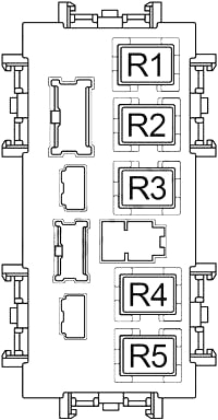
| No. |
Relay |
| R1 | Rear Window Defogger |
| R2 | Accessory |
| R3 | Power Socket |
| R4 | Ignition |
| R5 | Blower |
Engine Compartment Fuse Box No. 1
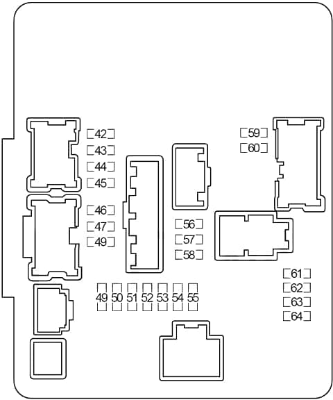
| No. |
A |
Circuit Protected |
| 42 | 10 | Right Headlamp (High Beam) |
| 43 | 10 | Left Headlamp (High Beam) |
| 44 | 15 | Right Headlamp (Low Beam) |
| 45 | 15 | Left Headlamp (Low Beam) |
| 46 | 10 | Engine Control Module (ECM), Mass Air Flow Sensors, EVAP Canister Purge Volume Control Solenoid Valve |
| 47 | 10 | EVAP Canister Vent Control Valve, Intake Valve Timing Control Solenoid Valve, Variable Valve Event and Lift (VVEL) Control Module |
| 48 | 15 | Air Fuel Ratio Sensors, Heated Oxygen Sensors |
| 49 | 15 | Ignition Coils, Condensor |
| 50 | 10 | Fuel Injectors, Engine Control Module (ECM) |
| 51 | 10 | Transmission Control Module (TCM) |
| 52 | 15 | Fuel Pump Relay |
| 53 | 10 | Cooling Fan Relay No.1 |
| 54 | 10 | ABS, Intelligent Cruise Control (ICC) Sensor, ICC Brake Hold Relay, Accelerator Pedal Actuator / Accelerator Pedal Position Sensor, Steering Angle Sensor, |
| 55 | 10 | Washer Pump |
| 56 | 30 | Front Wiper Relay |
| 57 | 15 | Front Fog Lamp Relay |
| 58 | 10 | Daytime Running Light Relay |
| 59 | 10 | Tail/Park Lamps (Left Side) |
| 60 | 10 | Tail/Park Lamps (Right Side), Map Lamps, Interior Lamps, Trunk Lid Opener Request Switch Assembly |
| 61 | 10 | A/C Relay |
| 62 | – | – |
| 63 | 15 | Throttle Control Motor Relay |
| 64 | 10 | Engine Control Module (ECM) |
Engine Compartment Fuse Box No.2
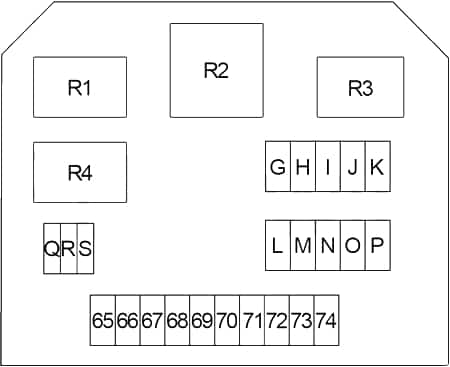
| No. |
A |
Circuit Protected |
| 65 | 10 | Vehicle Security Horn Relay |
| 66 | 15 | Horn Relay |
| 67 | 10 | Accelerator Pedal Actuator / Accelerator Pedal Position Sensor (with Intelligent Cruise Control (ICC)) |
| 68 | 10 | Transmission Control Module (TCM) |
| 69 | 10 | Alternator |
| 70 | 10 | All-Wheel Drive (AWD) Control Module |
| 71 | – | – |
| 72 | 10 | Daytime Running Light Relay |
| 73 | 10 | Daytime Running Light Relay |
| 74 | – | – |
| G | 60 | Direct Adaptive Steering: Steering Force Control Module |
| H | 100 | Direct Adaptive Steering: Steering Angle Sub Control Module |
| I | – | – |
| J | 100 | Direct Adaptive Steering: Steering Angle Main Control Module |
| K | – | – |
| L | 30 | ABS |
| M | 40 | Body Control Module (BCM), Circuit Breaker (Automatic Drive Positioner Control Unit, Power Seat) |
| N | 50 | ABS |
| O | 50 | Cooling Fan Relay No.1 |
| P | 50 | Variable Valve Event and Lift (VVEL) Actuator Motor Relay |
| Q | 30 | Pre-Crash Seat Belt Control Unit (Passenger Side) (with Intelligent Cruise Control (ICC)) |
| R | 30 | Ignition Relay (Fuse: “11”, “12”, “13”, “14”, “22”) |
| S | 30 | Pre-Crash Seat Belt Control Unit (Driver Side) (with Intelligent Cruise Control (ICC)) |
| Relay | ||
| R1 | Horn | |
| R2 | Cooling Fan No.1 | |
| R3 | Daytime Running Light | |
| R4 | Vehicle Security Horn | |
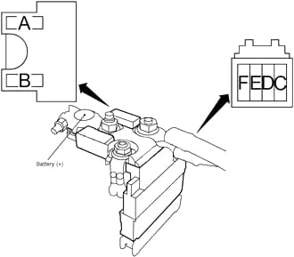
Fusible Link Block
| No. |
A |
Circuit Protected |
| A | 250 | Starter, Alternator, Fuse: “E”, “D”, “C” |
| B | – | – |
| F | 60 | Headlamp High Relay (Fuse: “42”, “43”), Headlamp Low Relay (Fuse: “44”, “45”), Tail Lamp Relay (Fuse: “59”, “60”), Fuse: “56”, “57”, “58” |
| E | 100 | Accessory Relay (Power Socket Relay, Fuse: “1”), Power Socket Relay (Fuse: “25”), Rear Window Defogger Relay (Fuse: “8”, “9”, “10”), Blower Relay (Fuse: “27”, “28”), Fuse: “2”, “3”, “4”, “5”, “6”, “7”, “15”, “17”, “19”, “20”, “30”, “32”, “33”, “36” |
| D | 80 | Engine Control Module (ECM) Relay (Fuse: “46”, “47”, “48”), Ignition Relay (Fuse: “49”, “50”, “51”, “52”, “53”, “54”, “55”), Fuse: “61”, “63”, “64” |
| C | 100 | Fuse: “65”, “66”, “67”, “68”, “69”, “70”, “72”, “73”, “G”, “H”, “J”, “L”, “M”, “N”, “O”, “P”, “Q”, “R”, “S” |
WARNING: Terminal and harness assignments for individual connectors will vary depending on vehicle equipment level, model, and market.