Infiniti QX60 (2012 – 2017) – fuse box diagram
Year of production: 2012, 2013, 2014, 2015, 2016, 2017
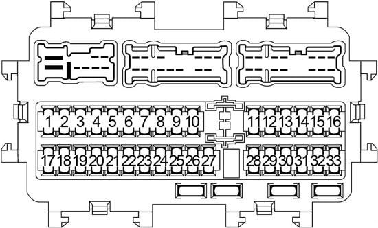
Passenger Compartment Fuse Box
| No. | A |
Circuit Protected |
| 1 | 10 | Body Control Module (BCM), Warning System Switch, Auto Anti-Dazzling Inside Mirror, Auto Light System, Automatic Drive Positioner Back-Up Lamp, Daytime Light System, Drive Assistance System, Front Fog Lamp, Front Wiper and Washer System, Headlamp, Headlamp Aiming System, Homelink Universal Transceiver, Illumination, Inside Mirror, Intelligent Key System/Engine Start Function, Interior Room Lamp, IVIS, Moonroof System, Parking Lamps, License Plate Lamps, Tail Lamps, Power Door Lock System, Power Seats, Power Window System, Rear Window Defogger, Rear Wiper and Washer System, Tire Pressure Monitoring System, Trailer Tow, Turn Signal and Hazard Warning Lamps, Vehicle Security System, Warning Chime System, Seat Memory Switch |
| 2 | 15 | Body Control Module (BCM) |
| 3 | 15 | Body Control Module (BCM), Power Door Lock System, Intellgent Key System/Engine Start Function, Vehicle Security System |
| 4 | 15 | Body Control Module (BCM), Power Door Lock System, Intellgent Key System/Engine Start Function, Vehicle Security System |
| 5 | – | – |
| 6 | – | – |
| 7 | – | – |
| 8 | – | – |
| 9 | 20 | Rear Cargo Power Socket |
| 10 | 10 | Stop Lamp Switch, Body Control Module (BCM), Intelligent Cruise Control (ICC) Brake Hold Relay, Engine Control Module (ECM) |
| 11 | 15 | Bose Audio Amplifier |
| 12 | 15 | Bose Audio Amplifier |
| 13 | 10 | Combination Meter |
| 14 | 5 | Air Conditioner Control, Drive Mode System, Heated Steering Wheel, Pre-Crash Seat Belt System, Rain Sensor |
| 15 | 15 | Audio System, AV Control Unit, Display Unit, Satellite Radio Tuner, Bluetooth Control Unit, Video Distributor, Rear Auxiliary Input Jacks, Headrest Display Unit, Telematic Control Unit (TCU) |
| 16 | 5 | Body Control Module (BCM) |
| 17 | 15 | Front Blower Motor |
| 18 | – | – |
| 19 | 20 | Cigarette Lighter |
| 20 | 20 | Rear Console Power Socket |
| 21 | 20 | Front Console Power Socket |
| 22 | 10 | Door Mirror Defogger |
| 23 | 15 | Rear Window Defogger |
| 24 | 15 | Rear Window Defogger |
| 25 | 10 | Intelligent Key Warning Buzzer, Push-Button Ignition Switch, All-Wheel Drive (AWD) Control Module, Data Link Connector, Remote Keyless Entry Receiver, Seatback Power Return Control Unit, Transmission Control Module (TCM) |
| 26 | 5 | Headlamp Aiming Switch |
| 27 | 15 | Front Blower Motor |
| 28 | 15 | 2nd Row Heated Seat |
| 29 | 5 | Audio System, AV Control Unit, Around View Monitor Control Unit, Telematic Control Unit (TCU), Sonar Control Unit, Auto Anti-Dazzling Inside Mirror, Trailer Tow Relay No.1, Trailer Tow Relay No.2, Trailer Back-Up Relay, Heated Seat Relay, Climate Controlled Seat Relay |
| 30 | 10 | Bluetooth Control Unit, Advanced Driver Assistance Systems (ADAS) Control Unit, Intelligent Cruise Control (ICC) Sensor, ICC Brake Hold Relay, Brake Pedal Position Switch, Engine Control Module (ECM), Warning Buzzer, Side Radar (LH/RH), Lane Camera Unit, Data Link Connector, Electronic Controlled Engine Mount Control Solenoid Valve, Air Conditioner Control, Ionizer, Exhaust Gas/Outside Odor Detecting Sensor, PTC Relay No.1, PTC Relay No.2, A/C 120V Outlet Main Switch, Power Seat |
| 31 | 5 | Combination Meter |
| 32 | 10 | Air Bag Diagnosis Sensor Unit, Occupant Classification System Control Unit |
| 33 | – | – |
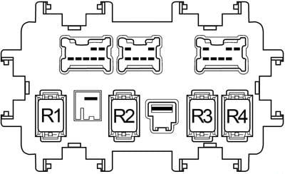
| No. |
Relay |
| R1 | Ignition No.2 |
| R2 | Blower Motor |
| R3 | Rear Window Defogger |
| R4 | Accessory No.1 |
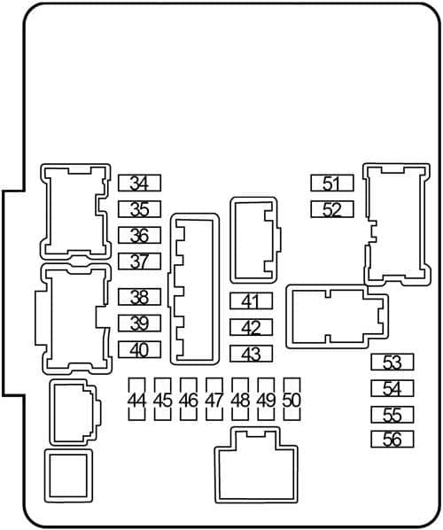
Engine Compartment Fuse Box No. 1
| No. |
A |
Circuit Protected |
| 34 | 10 | Right Headlamp (High Beam) |
| 35 | 10 | Left Headlamp (High Beam) |
| 36 | 15 | Right Headlamp (Low Beam) |
| 37 | 15 | Left Headlamp (Low Beam) |
| 38 | 10 | Engine Control Module (ECM), VIAS Control Solenoid Valve, EVAP Canister Vent Control Valve, Throttle Control Motor Relay |
| 39 | 10 | Engine Control Module (ECM), EVAP Canister Purge Volume Control Solenoid Valve, Intake Valve Timing Control Solenoid Valve, Intake Valve Timing Intermediate Lock Control Solenoid Valve, Exhaust Valve Timing Control Solenoid Valve, Mass Air Flow Sensor |
| 40 | 15 | Heated Oxygen Sensors, Air Fuel Ratio Sensors |
| 41 | 30 | Front Wiper Relay |
| 42 | 15 | Front Fog Lamp Relay |
| 43 | 10 | Daytime Running Light Relay |
| 44 | 15 | Ignition Coils, Condenser, Engine Control Module (ECM) |
| 45 | 10 | Fuel Injectors, Engine Control Module (ECM) |
| 46 | 10 | Transmission Range Switch, Transmission Control Module (TCM), Primary Speed Sensor, Input Speed Sensor, Output Speed Sensor |
| 47 | 15 | Fuel Pump Relay |
| 48 | 10 | Cooling Fan Relay, Headlamp Aiming Motors, Headlamp Aiming Switch, Transmission Range Sensor |
| 49 | 10 | All-Wheel Drive (AWD) Control Unit, Power Steering Control Module, ABS Solenoid Valve Relay, ABS Motor Relay, Steering Angle Sensor, Yaw Rate/Side/Decel G Sensor |
| 50 | 10 | Front and Rear Washer System, Combination Switch |
| 51 | 10 | Tail Lamps, License Plate Lamps, Trailer Tow Relay No.1, Headlamp Aiming Switch, Glove Box Lamp, Illumination |
| 52 | 10 | Parking Lamps, Side Marker Lamps |
| 53 | 10 | A/C Relay |
| 54 | – | – |
| 55 | 15 | Throttle Control Motor Relay |
| 56 | 10 | Engine Control Module (ECM) |
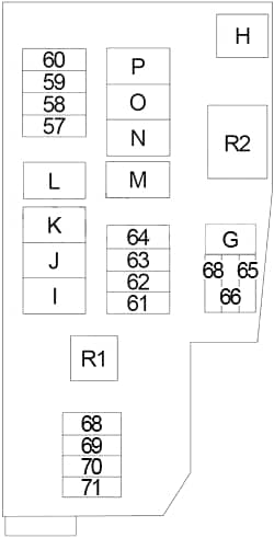
Engine Compartment Fuse Box No.2
| No. |
A |
Circuit Protected |
| 57 | 10 | Alternator, Anti Theft Horn Relay |
| 58 | 10 | BOSE Audio System |
| 59 | 30 | PTC Relay No.1 (PTC Heater) |
| 60 | 30 | PTC Relay No.2 (PTC Heater) |
| 61 | 30 | Trailer Tow Relay No.2 (Trailer Receptacle) |
| 62 | 10 | All-Wheel Drive (AWD) Control Unit |
| 63 | 15 | Horn Relay, Intelligent Key System |
| 64 | 30 | Seatback Power Return Control Unit |
| 65 | 10 | Accessory Relay No.2 (AV Control Module, Satellite Radio Tuner, A/C and AV Switch Assembly, Bluetooth Control Unit, Power Seat, Around View Monitor Control Unit, Video Distributor, Rear Auxiliary Input Jacks, Telematic Control Unit (TCU), Telematics Switch, Power Mirror Remote Control Switch, Combination Meter) |
| 66 | 15 | Passenger Side: Climate Controlled Seat, Heated Seat |
| 67 | 10 | Trailer Tow Relay No.1 (Trailer Receptacle) |
| 68 | 15 | Driver Side: Climate Controlled Seat, Heated Seat |
| 69 | 30 | Inverter System |
| 70 | 20 | Rear Blower Motor Relay |
| 71 | 20 | Rear Blower Motor Relay |
| G | 30 | Electric Brake (Trailer) |
| H | 60 | Cooling Fan Relay |
| I | 50 | ABS (Motor Relay) |
| J | 30 | ABS (Solenoid Valve Relay) |
| K | 40 | Ignition Relay No.2 (Fuse: “28”, “29”, “30”, “31”, “32”), Starter Relay, Starter Control Relay |
| L | 30 | Pre-Crash Seat Belt System (Driver Side) |
| M | 30 | Pre-Crash Seat Belt System (Passenger Side) |
| N | 40 | Automatic Back Door System |
| O | 40 | Body Control Module (BCM), Auto Light System, Automatic Back Door System, Back-Up Lamp, CVT Shift Lock System, Daytime Light System, Front Fog Lamp, Front Wiper and Washer System, Headlamp, Headlamp Aiming System, Heated Steering Wheel, Illumination, Intelligent Key System/Engine Start Function, Intelligent Key System, Interior Room Lamp, IVIS, Moonroof System, Parking Lamps, License Plate Lamps, Tail Lamps, Power Door Lock System, Power Seats, Power Window System, Rear Window Defogger, Rear Wiper and Washer System, Tire Pressure Monitoring System, Trailer Tow, Turn Signal and Hazard Warning Lamps, Vehicle Security System, Warning Chime System, Automatic Drive Positioner, Tilt & Telescopic Steering Column |
| P | – | – |
| Relay | ||
| R1 | Horn | |
| R2 | Cooling Fan | |
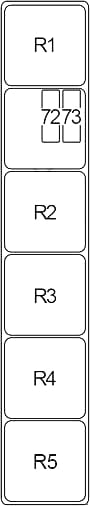
Engine Compartment Relay Box No.1
| No. |
A |
Circuit Protected |
| 72 | 10 | Trailer Back-Up Relay |
| 73 | 15 | Trailer Tow Turn Relay (LH), Trailer Tow Turn Relay (RH) |
| 74 |
10 |
Heated Steering Relay |
| Relay | ||
| R1 | PTC No.2 | |
| R2 | Intelligent Cruise Control (ICC) Brake Hold | |
| R3 | Accessory No.2 | |
| R4 | – | |
| R5 | PTC No.1 | |
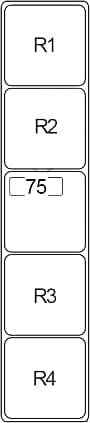
Engine Compartment Relay Box No.2
| No. |
A |
Circuit Protected |
| 75 |
10 |
Driver Assistance System |
| Relay | ||
| R1 | – | |
| R2 | – | |
| R3 | – | |
| R4 | Daytime Running Light | |
Fusible Link Block
| No. |
A |
Circuit Protected |
| A | 250 | Generator, Starter, Fuse: “B”, “C”, “D” |
| B | 100 | Fuse: “57”, “58”, “59”, “60”, “61”, “62”, “63”, “64”, “72”, “73”, “H”, “I”, “J”, “K”, “L”, “M”, “N”, “O” |
| C | 80 | Headlamp High Relay (Fuse: “34”, “35”), Headlamp Low Relay (Fuse: “36”, “37”), Tail Lamp Relay (Fuse: “51”, “52”), Fuse: “41”, “42”, “43”, “68”, “69”, “70”, “71” |
| D | 100 | Power Steering Control Module |
| E | 80 | Engine Control Module Relay (Fuse: “38”, “39”, “40”), Ignition Relay No.1 (Fuse: “44”, “45”, “46”, “47”, “48”, “49”, “50”) Fuse: “53”, “55”, “56” |
| F | 100 | Accessory Relay No.1 (Fuse: “19”, “20”, “21”), Rear Window Defogger Relay (Fuse: “22”, “23”, “24”), Blower Motor Relay (Fuse: “17”, “27”), Fuse: “1”, “2”, “3”, “4”, “9”, “10”, “11”, “12”, “13”, “14”, “15”, “16”, “25”, “65”, “66”, “67”, “G” |
WARNING: Terminal and harness assignments for individual connectors will vary depending on vehicle equipment level, model, and market.