Mercury Mystique (1995 – 2000) – fuse box diagram
Year of production: 1995, 1996, 1997, 1998, 1999, 2000
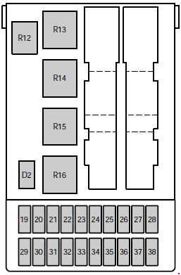
Passenger Compartment Fuse Box
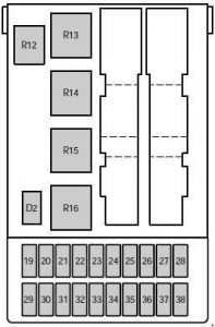 Mercury Mystique – fuse box diagram – passenger compartment
No.
|
A
|
Fused component
|
| 19 |
7.5 |
’95-’97: Heated rear view mirrors |
| 20 |
10 |
Circuit breaker: Wiper motors |
| 21 |
40 |
Power windows |
| 22 |
7.5 |
’95-’99: ABS module |
| 23 |
15 |
Backup lamps |
| 24 |
15 |
Brake lamps |
| 25 |
20 |
Door locks |
| 26 |
7.5 |
Main light |
| 27 |
15 |
Cigar lighter |
| 28 |
30 |
Electric seats |
| 29 |
30 |
Rear window defrost |
| 30 |
7.5 |
Engine management system |
| 31 |
7.5 |
Instrument panel illumination |
| 32 |
7.5 |
Radio |
| 33 |
7.5 |
Parking lamps – driver’s side |
| 34 |
7.5 |
Interior lighting/electric mirror adjustment |
| 35 |
7.5 |
Parking lamps – passenger’s side |
| 36 |
10 |
’95-’98: Air bag |
| 37 |
30 |
Heater blower motor |
| 38 |
— |
Not used |
| Relay |
| R12 |
Interior lighting |
| R13 |
Rear window defrost |
| R14 |
Heater blower motor |
| R15 |
Wiper motor |
| R16 |
Ignition |
| Diode |
| D2 |
Reverse voltage protection |
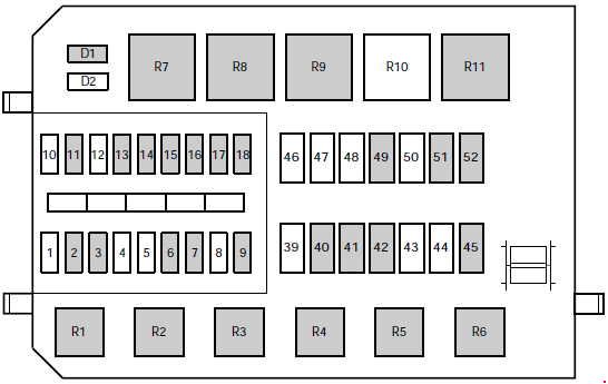
Engine Compartment Fuse Box (’99-’00)
 Mercury Mystique – fuse box diagram – engine compartment
No.
|
A
|
Fused component
|
| 1 |
— |
Not used |
| 2 |
7.5 |
Alternator |
| 3 |
20 |
Foglamps |
| 4 |
— |
Not used |
| 5 |
— |
Not used |
| 6 |
3 |
EEC ignition module (memory) |
| 7 |
20 |
Horn and hazard flasher warning system |
| 8 |
— |
Not used |
| 9 |
15 |
Fuel pump |
| 10 |
— |
Not used |
| 11 |
20 |
Ignition, Electronic Engine Control |
| 12 |
— |
Not used |
| 13 |
20 |
HEGO sensor |
| 14 |
7.5 |
ABS module |
| 15 |
7.5 |
Low beam headlamp (passenger’s side) |
| 16 |
7.5 |
Low beam headlamp (driver’s side) |
| 17 |
7.5 |
High beam headlamp (passenger’s side) |
| 18 |
7.5 |
High beam headlamp (driver’s side) |
| 39 |
— |
Not used |
| 40 |
20 |
Ignition, light switch, central junction box |
| 41 |
20 |
EEC relay |
| 42 |
40 |
Central junction box (fuse 37 to blower relay) |
| 43 |
— |
Not used |
| 44 |
— |
Not used |
| 45 |
60 |
Ignition |
| 46 |
— |
Not used |
| 47 |
— |
Not used |
| 48 |
— |
Not used |
| 49 |
60 |
Engine cooling |
| 50 |
— |
Not used |
| 51 |
60 |
ABS |
| 52 |
60 |
Central junction box (central timer module, rear window defrost relay, fuses 24, 25, 27, 28, 34) |
| Relay |
| R1 |
Fuel pump |
| R2 |
EEC module |
| R3 |
Air conditioning |
| R4 |
Low beam |
| R5 |
High beam |
| R6 |
Horn |
| R7 |
Starter solenoid |
| R8 |
Engine cooling fan (high speed) |
| R9 |
Engine cooling fan |
| R10 |
Not used |
| R11 |
Daytime running lights |
| Diode |
| D1 |
Reverse voltage protection |
| D2 |
Not used |
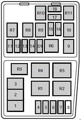
Engine Compartment Fuse Box (’95-’98)
 Mercury Mystique – fuse box diagram – engine compartment
No.
|
A
|
Fused component
|
| 1 |
80 |
Main power supply to vehicle electrical system |
| 2 |
60 |
Engine cooling fan |
| 3 |
60 |
ABS braking system, heater blower (’98) |
| 4 |
20 |
Ignition, Daytime running lights |
| 5 |
15 |
Foglamp |
| 6 |
— |
Not used |
| 7 |
20 |
’98: ABS system |
| 30 |
’95-’97: ABS system |
| 8 |
30 |
’95-’97: Air pump |
| 9 |
20 |
Electronic Engine Control (EEC) |
| 10 |
20 |
Ignition switch |
| 11 |
3 |
EEC ignition module (memory) |
| 12 |
15 |
Horn and hazard flasher warning system |
| 13 |
20 |
’98: HEGO sensor |
| 15 |
’95-’97: HEGO sensor |
| 14 |
15 |
Electrically operated fuel pump |
| 15 |
10 |
Low beam headlamp – (passengers side) |
| 16 |
10 |
Low beam headlamp – (driver’s side) |
| 17 |
10 |
High beam headlamp – (passengers side) |
| 18 |
10 |
High beam headlamp – (driver’s side) |
| Relay |
| R1 |
Daytime running lights |
| R2 |
Radiator fan relay (high speed) |
| R3 |
Air conditioning |
| R4 |
Air conditioning clutch relay |
| R5 |
Radiator fan relay (low speed) |
| R6 |
Starter solenoid |
| R7 |
Horn |
| R8 |
Fuel pump |
| R9 |
Low beam headlamps |
| R10 |
High beam headlamps |
| R11 |
PCM module |
| Diode |
| D1 |
Reverse voltage protection |
Auxiliary relays (outside of fuse boxes (’99-’00))
No.
|
Circuits switched
|
Location
|
| R18 |
“One touch” switch (drivers window) |
Driver’s door |
| R22 |
Foglamps |
Wire shield on instrument panel |
| R23 |
Turn signals |
Steering column |
| R24 |
Panic alarm – driver’s side |
Door lock module bracket |
| R25 |
Panic alarm – right-hand side |
Door lock module bracket |
| R32 |
Hego heater control (’00) |
Near PCM-Module |
WARNING: Terminal and harness assignments for individual connectors will vary depending on vehicle equipment level, model, and market.