Mercury Villager (1999 – 2002) – fuse box diagram
Year of production: 1999, 2000, 2001, 2002
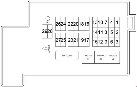
Passenger Compartment Fuse Box
 Mercury Villager – fuse box diagram – passenger compartment
| № |
Fuse |
A |
Description
|
| 1 |
Corner Lamps |
10 |
Front Exterior Lamps |
| 2 |
Heated Seat |
7.5 |
Heated Seats |
| 3 |
I/P Ilium |
7.5 |
Interior Panel Illumination Lamps |
| 4 |
Electron |
10 |
Transaxle Control Module (TCM), Electronic Automatic Temperature Control (EATC) Module, Instrument Cluster, Rear Wiper Motor Assembly |
| 5 |
Tail Lamp |
10 |
Rear Exterior Lamps |
| 6 |
Air Bag |
10 |
Airbag Diagnostic Monitor |
| 7 |
Audio |
10 |
Radio, Rear Radio Control, CD Changer |
| 8 |
Eng Cont |
10 |
Powertrain Control Module, Oxygen Sensors |
| 9 |
Room Lamp |
15 |
Interior Lamps |
| 10 |
Mirror |
7.5 |
Smart Entry Control (SEC), Power Mirror Switch |
| 11 |
Stop Lamp |
20 |
Brake Pedal Position (BPP) Switch, Trailer Tow Control Unit |
| 12 |
Cigar Lighter |
20 |
Cigar Lighter |
| 13 |
Hazard |
10 |
Hazard Warning Flasher Switch, Anti-Theft Indicator |
| 14 |
RR Pwr Plug |
20 |
Rear Powerpoint |
| 15 |
Rear Blower |
15 |
Rear Blower Motor Relay, Rear Blower Motor |
| 16 |
Wiper |
20 |
Front Wiper/Washer Assembly |
| 17 |
Rear Blower |
15 |
Rear Blower Motor Relay, Rear Blower Motor |
| 18 |
Rear Wiper |
10 |
Rear Wiper/Washer Assembly |
| 19 |
02 Sensor |
7.5 |
Oxygen Sensor |
| 20 |
Audio |
7.5 |
’99-’00: Radio |
| Audio/Video |
15 |
’01-’02: Radio/Video System |
| 21 |
Turn |
10 |
Hazard Warning Flasher Switch |
| 22 |
Audio Amp |
20 |
Subwoofer Amplifier |
| 23 |
Front Blower |
20 |
Front Blower Motor, Front Blower Motor/Speed Controller |
| 24 |
Eng Cont |
7.5 |
Powertrain Control Module, Lighting Control Module |
| 25 |
Relays |
10 |
Speed Control, Instrument Cluster, Rear Blower Motor, Data Link Connector #2, Cooling Fans |
| 26 |
A/C Cont |
7.5 |
Electronic Automatic Temperature Control (EATC) Module, A/C Relay, Front Climate Control Panel |
| 27 |
Electron |
10 |
Transmission Control, Lighting Control Module, ABS Control Module, Smart Entry Control (SEC)/Timer Module |
| 28 |
Rear Defog |
20 |
Rear Window Defrost |
| 29 |
Front Blower |
20 |
Front Blower Motor, Front Blower |Motor/Speed Controller |
| 30 |
Rear Defog |
20 |
Rear Window Defrost |
| 31 |
— |
— |
Not Used |
| 32 |
Heated Mirror |
10 |
Rear Window Defrost Switch, Power/Heated Mirrors |
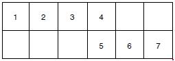
Engine compartment main fuse panel
 Mercury Villager – fuse box diagram – engine compartment
| № |
Fuse |
A |
Description
|
| 1 |
FOG LAMP |
7.5 |
’01-’02: Fog Lamps |
| 2 |
FUEL PUMP |
15 |
Fuel Pump Relay |
| 3 |
INJ |
10 |
Powertrain Control Module (PCM), Injectors |
| 4 |
SEC |
7.5 |
Anti-Theft Relay, Smart Entry Control (SEC)/Timer Module |
| 5 |
RAD |
7.5 |
Radiator Fan Sensing |
| 6 |
ECCS |
10 |
Data Link Connector (DLC) #1, PCM Power Relay |
| 7 |
— |
— |
Not Used |
| 8 |
— |
— |
Not Used |
| 9 |
ALT |
10 |
Generator |
| 10 |
ABS |
20 |
ABS Control Module |
| 11 |
— |
— |
Not Used |
| 12 |
H/L RH |
15 |
Lighting Control Module |
| 13 |
HORN |
15 |
Horn Relay |
| 14 |
— |
— |
Not Used |
| 15 |
H/L LH |
15 |
Lighting Control Module |
| 16 |
— |
— |
Not Used |
| 17 |
— |
— |
Not Used |
| 18 |
ABS |
40 |
ABS Control Module |
| 19 |
— |
— |
Not Used |
| 20 |
PWR WND |
30 |
Power Window Relay, Smart Entry Control (SEC)/Timer Module, Power Seats |
| 21 |
RAD FAN LO |
20 |
Low Speed Fan Control Relay |
| 22 |
— |
— |
Not Used |
| 23 |
IGN SW |
30 |
Ignition Switch |
| 24 |
— |
— |
Not Used |
| 25 |
RAD FAN |
75 |
High Speed Fan Control Relay |
| 26 |
FR BLW |
65 |
Front Blower Motor Relays |
| 27 |
RR DEF |
45 |
Rear Window Defroster Relay |
| 28 |
ALT |
140 |
Accessory Relay, Ignition Relay, Tail Lamp Relay, Fuse Junction Panel |
| 29 |
MAIN |
100 |
Generator |
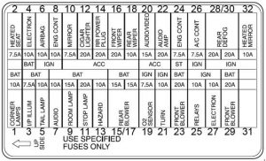
Additional Relay Box
 Mercury Villager – fuse box diagram – additional relay box
| № |
Relay |
| 1 |
Start Inhibit |
| 2 |
Fuel Pump |
| 3 |
Bulb Check |
| 4 |
’99-’00: Speed Control Hold |
| ’01-’02: Fog Lamp |
| 5 |
Anti-theft |
| 6 |
Horn |
| 7 |
A/C |
WARNING: Terminal and harness assignments for individual connectors will vary depending on vehicle equipment level, model, and market