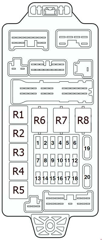
| No. |
A |
Load circuit |
| 1 |
60 |
Fuse No.15, 16, 19, 20 (in junction block) circuit |
| 2 |
50 |
Fan controller |
| 3 |
60 |
ABS-ECU |
| 4 |
40 |
Ignition switch circuit |
| 5 |
30 |
Power window main switch and power window sub switch |
| 6 |
15 |
Front fog lamp, front fog lamp indicator lamp, front fog lamp relay and spare connector (for front fog lamp) |
| 7 |
10 |
Horn relay and horn |
| 8 |
20 |
Air cleaner air flow sensor, camshaft position sensor, emission solenoid valve (EGR system), emission solenoid valve (purge control system), engine-A/T-ECU, engine-ECU, engine control oxygen sensor, engine control relay, engine crank angle sensor, fan control relay, fuel injector, ignition coil relay, immobilizer-ECU and throttle body idle speed control servo |
| 9 |
10 |
A/C compressor |
| 10 |
15 |
ABS-ECU, engine-A/T-ECU, high mount stop lamp and rear combination lamp |
| 11 |
15 |
Accessory socket |
| 12 |
7.5 |
Alternator |
| 13 |
10 |
ETACS-ECU, front turn signal lamp, rear combination lamp, side turn signal lamp and turn signal indicator lamp |
| 14 |
20 |
A/T control solenoid valve assembly and engine-A/T-ECU |
| 15 |
15 |
Fuel pump |
| 16 |
10 |
Headlamp (RH) |
| 17 |
10 |
Headlamp (LH) and high beam indicator lamp |
| 18 |
10 |
Headlamp (RH) |
| 19 |
10 |
Headlamp (LH), headlamp assembly and headlamp levelling switch |
| 20 |
7.5 |
A/C-ECU, ashtray illumination lamp, cigarette lighter illumination lamp, combination meter, fog lamp switch, front turn signal lamp, hazard warning switch, headlamp assembly (RH), headlamp levelling switch, heated seat switch, heater control unit, licence plate lamp, rear combination lamp, rheostat, side turn signal lamp and spare connector (for audio) |
| 21 |
7.5 |
Combination meter, headlamp assembly (LH), licence plate lamp, position lamp (LH) and rear combination lamp (LH) |
| 22 |
10 |
Combination meter, column switch, ETACS-ECU and front-ECU |
| 23 |
10 |
Clock, ETACS-ECU and spare connector (for audio) |
| 24 |
– |
– |
| 25 |
20 |
Heated seat assembly and heated seat switch |
| 26 |
100 <4G1> 120 <4G6> |
Battery, fusible link No.1,2, 3, 4, 5, fuse No.6, 7, 8, 9, 10, 11, 12, 13, 14, 15, 22 (relay box) and front-ECU |
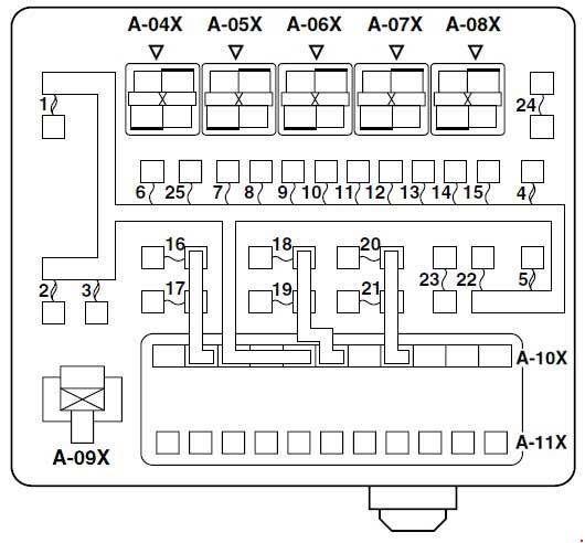
| Relays |
| A-04X |
Front fog lamp relay |
| A-05X |
Horn relay |
| A-06X |
– |
| A-07X |
– |
| A-08X |
– |
| A-09X |
Fan control relay |
| A-10X |
Front-ECU |
| A-11X |
Front-ECU |