Mitsubishi Lancer (2007 – 2017) – fuse box diagram
Year of production: 2007, 2008, 2009, 2010, 2011, 2012, 2013, 2014, 2015, 2016, 2017
Engine compartment fuse box
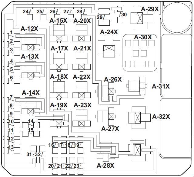
| No. | A | Load circuit |
| 1 | 15 | Fog light and fog light relay |
| 2 | 7.5 | Engine control module |
| 3 | 20 | Primary pulley speed sensor <CVT>, secondary pulley speed sensor <CVT> and transaxle control module <CVT> |
| 4 | 10 | Horn and horn relay |
| 5 | 7.5 | Generator |
| 6 | 20 | Headlight washer |
| 7 | 10 | A/C compressor assembly and A/C compressor clutch relay |
| 8 | 15 | ETV/Oil cooler fan (Twin Clutch SST) (except for vehicles with turbocharger) ETV (vehicles with turbocharger) |
| 9 | 20 | Security horn |
| 10 | 15 | Wiper deicer |
| 11 | – | – |
| 12 | 30 | Power gate |
| 13 | 10 | Daytime running light and daytime running light relay |
| 14 | 10 | Headlight assembly (High: LH) |
| 15 | 10 | Headlight assembly (High: RH) |
| 16 | 20 | Headlight (low/high beam) (left) |
| 17 | 20 | Headlight (low/high beam) (right) |
| 18 | 10 | Headlight assembly (Low: LH) |
| 19 | 10 | Headlight assembly (Low: RH) |
| 20 | 10 | ENG/POWER (except for vehicles with turbocharger) I/C SPRAY (vehicles with turbocharger) |
| 21 | 10 | Ignition coil No.1 to 4 |
| 22 | 20 | Center exhaust pipe heated oxygen sensor, engine control module, engine oil control valve, evaporative emission purge solenoid, evaporative emission ventilation solenoid, injector No.1 to 4, mass airflow sensor, heated oxygen sensor and vehicle speed sensor <M/T> |
| 25 | Fuel line heater | |
| 23 | 15 | Fuel pump module (except for vehicles with turbocharger) |
| 20 | Fuel pump module (vehicles with turbocharger) | |
| 24 | 30 | Starter |
| 25 | 40 | Valve lift control (except for vehicles with turbocharger) |
| 26 | 40 | ABS-ECU |
| 27 | 30 | ABS-ECU |
| 28 | 30 | Condenser fan motor, condenser fan relay and fan control relay |
| 29 | 40 | Radiator fan motor and radiator fan relay |
| 30 | 30 | IOD, Fuse No.7 to 9 in passenger compartment |
| 31 | 30 | Audio amplifier |
| 32 | 30 | Diesel |
| No. |
Relays | |
| A-11X | Fog light relay | |
| A-12X | Horn relay | |
| A-13X | A/C compressor clutch relay | |
| A-14X | – | |
| A-15X | CVT control relay | |
| A-16X | – | |
| A-17X | Headlight relay (High) | |
| A-18X | Throttle actuator control motor relay | |
| A-19X | – | |
| A-20X | Daytime running light relay | |
| A-21X | Injector relay | |
| A-22X | – | |
| A-23X | Condenser fan relay | |
| A-24X | Stater relay | |
| A-25X | Headlight relay (Low) | |
| A-26X | Radiator fan relay | |
| A-27X | – | |
| A-28X | Fan control relay | |
| A-29X | – | |
| A-30X | MFI relay | |
Fuse box above battery
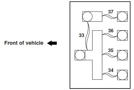
| No. | A | Load circuit |
| 33 | 120 | Fusible link No.37/ Fusible link No.34 to 36 |
| 34 | 80 | Fuse Nos.2, 4, 5, 10, 11,12, 14, 15, 17, 18, 20 and No.25 in passenger compartment |
| 35 | 80 | – |
| 36 | 120 | Fuse No.1 to 32 in engine compartment, headlight relay (High), headlight relay (Low) and MFI relay |
| 37 | 80 | Fusible link No.1 and 21, Fuse No. 3, 6, 13, 16, 19, and 22 in passenger compartment and ETACS-ECU(ACC relay 2 and blower relay) |
Instrument Panel Fuse Block
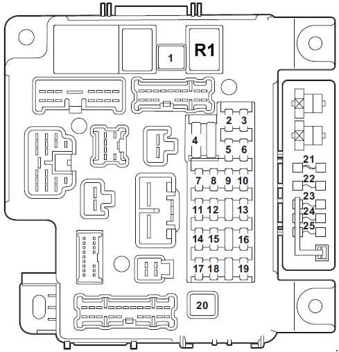
| No. | A | Load circuit |
| 1 | 30 | Blower motor |
| 2 | 15 | Stop lights (Brake lights), ETACS-ECU, high-mounted stoplight, rear combination light and shift switch assembly |
| 3 | 10 | Rear fog light |
| 4 | 30 | ETACS-ECU, washer motor and windshield wiper motor |
| 5 | 10 | Data link connector |
| 6 | 20 | ETACS-ECU, front door lock actuator, trunk lid actuator and switch and rear door lock actuator |
| 7 | 15 | Audio visual navigation unit, CAN box unit, center panel unit, hands free module, radio and CD player or CD changer, rear display unit and satellite radio tuner |
| 8 | 7.5 | A/C-ECU, column switch, combination meter, ETACS-ECU, key reminder switch, KOS-ECU, power window relay, wireless control module <vehicles with KOS> and receiver antenna module <vehicles without KOS> |
| 9 | 15 | Audio visual navigation unit, center panel unit, combination meter and key reminder switch |
| 10 | 15 | ETACS-ECU, Hazard warning flasher |
| 11 | 15 | Rear window wiper |
| 12 | 7.5 | A/C control panel, A/C-ECU, CVT control relay, ABS-ECU, center panel unit, column switch, combination meter, heated seat relay, KOS-ECU, rear window defogger relay, shift switch assembly, SRS-ECU, sunroof motor assembly, wireless control module <vehicles without KOS> and receiver antenna module <vehicles with KOS> |
| 13 | 15 | Accessory socket (front floor console) and cigarette lighter |
| 14 | 10 | Ignition switch circuit |
| 15 | 20 | Sunroof motor assembly |
| 16 | 10 | Audio visual navigation unit, CAN box unit, door mirror assembly, radio and CD player or CD changer, rear display unit and remote controlled mirror switch |
| 17 | 10 | Occupant classification-ECU |
| 18 | 7.5 | Audio visual navigation unit, backup light switch <M/T>, transaxle control module <CVT>, SRS-ECU and transmission range switch <CVT> |
| 19 | 15 | Accessory socket (rear floor console) |
| 20 | 30 | Front power window motor (RH), power window main switch and rear power window motor |
| 21 | 30 | Rear window defogger |
| 22 | 7.5 | Door mirror assembly |
| 23 | 15 | 115V Power outlet |
| 24 | 20 25 |
Power seats |
| 25 | 30 | Heated seat |
| No. | Relays | |
| R1 | Blower motor | |
WARNING: Terminal and harness assignments for individual connectors will vary depending on vehicle equipment level, model, and market.