Peugeot 405 – fuse box diagram
Year of production:
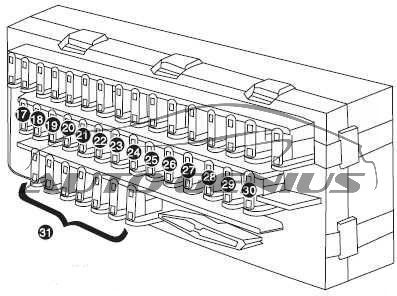
Fuse box on the dashboard
Fuse box is situated under the dashboard to the left hand side of the Driver which included six spare fuses plus special vise for changing fuses.
| № |
A |
Protected Component |
| F1 | 10 | Radio / CD player power supply after main switch |
| F2 | 5 | Relay compressor cut – electricity after ceiling light timer switch – key has three versatile |
| F3 | 15 | After the power switch modulator ABS – high speed fan relays |
| F4 | 10 | Small LED rear right – Buzzer signal relay power-lighting |
| F5 | 15 | Relay Fans – feeding after switch intelligent ventilation system |
| F6 | 10 | Air bag power supply |
| F7 | 20 | Horn Relay-fog lamp-horn |
| F8 | — | Shunt: Input shunt switches |
| F9 | 10 | Front small lights, Rear small lights left, Rear plaque light |
| F10 | 30 | Rear window lifter – Window switches back lighting |
| F11 | 30 | MAIN FUSE related to front light- low and high beam lights- the relay front/rear fog lamp |
| F12 | 10 | Reverse lights – rear obstacle warning unit – after the switch forward power amplifiers – feeding after room temperature sensor switch – switch power after DIAG – feeding after ABS alarm relay |
| F13 | 30 | No consumption |
| F14 | 30 | No consumption |
| F15 | 15 | Power LED ceiling lights front and rear – power unit central locking – power folding mirror unit – electric permanent timers roof – lights trunk – relay ejector trunk |
| F16 | 20 | Lighter. continual power supply after main switch |
| F17 | 10 | Permanent power unit intelligent ventilation system – Memory radio |
| F18 | 10 | Rear fog lamp |
| F19 | 10 | Panel lighting – Front lighting Amp – Brightness panel radio keys – Lighting control system on the steering wheel (MFC) – Lighter lighting – Lighting controllers, electric mirrors |
| F20 | 30 | Power driver seat |
| F21 | 30 | Smart fan ventilation system |
| F22 | 20 | Power passenger seat |
| F23 | 15 | No consumption |
| F24 | 30 | Motor for Wipers – Wiper lever – Power unit glass wiper and washer pump |
| F25 | 15 | Forward permanent power amplifiers – a permanent power DIAG |
| F26 | 15 | Flash unit – a permanent electricity panel radio buttons |
| F27 | 30 | Rear glass heater – Side mirrors heater |
| F28 | 15 | Brake lights – front window lift relay – panel power after switch keys radio |
| F29 | 30 | Window lifter front – Lighting glass front lift key |
| F30 | 15 | Map reading light – Steering indicator circuit power supply – The power relay – Glove compartment light – Rear window lifter relay – Relay locking rear lift glass child – Lighting rear lift glass – Automatic window lifter unit – Electric mirror |
| F31 | — | Spare fuses |
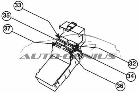
Fuse box in engine compartment
| № |
A |
Protected Component |
| F32 | 30 | Fan for engine |
| F33 | 30 | Fan for engine |
| F34 | 30 | Spare fuse |
| F35 | 30 | Spare fuse |
| F36 | — | Short circuit connection – Power supply for fuse box and main switch |
| F37 | — | Short circuit connection – Power supply for fusebox |
WARNING: Terminal and harness assignments for individual connectors will vary depending on vehicle equipment level, model, and market.