Renault Duster – fuse box diagram
Year of production:
Passenger Compartment Fuse Box
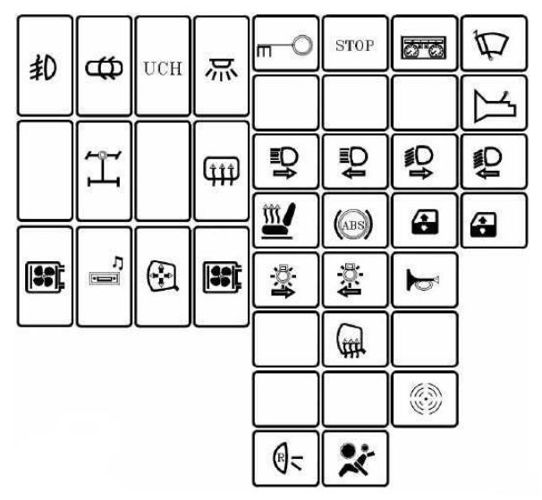
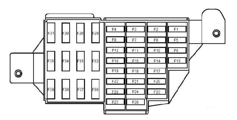
| Number | Ampere rating [A] | Allocation |
| F1 | 20 | Windscreen wiper motor – screen wash/wipe combination switch – UCH |
| F2 | 5 | Instrument panel – fuel pump relay control on board – injection computer |
| F3 | 10 | Brake light switch |
| F4 | 10 | UCH – diagnostic socket – transponder unit – shift pattern control – anti-theft tracker unit |
| F5 | 5 | Automatic gearbox electric control unit – starter relay control – front/rear torque distribution electric control unit |
| F6 | — | — |
| F7 | — | — |
| F8 | — | — |
| F9 | 10 | Left-hand dipped beam headlight – instrument panel |
| F10 | 10 | Right-hand dipped headlight |
| F11 | 10 | Left-hand main beam headlight – instrument panel |
| F12 | 10 | Right-hand main beam headlight |
| F13 | 30 | Driver’s dual rear electric window control – child safety relay control |
| F14 | 30 | Driver’s dual front electric window control |
| F15 | 10 | Anti-lock braking system ECU |
| F16 | 15 | Radio |
| F17 | 15 | Main electromagnetic horn – secondary electromagnetic horn |
| F18 | 10 | Rear left-hand side light – front left-hand side light |
| F19 | 10 | Rear right-hand side light – passenger storage compartment light – instrument panel – UCH – hazard warning lights control – air conditioning control panel – radio – central door locking switch – first row cigarette lighter – 4×4 mode control – right-hand number plate light – left-hand number plate light – front right-hand side light – traction control switch – heated rear screen control – parking proximity sensor switch |
| F20 | 7,5 | Rear fog light |
| F21 | 5 | Instrument panel |
| F22 | — | — |
| F23 | 15 | Fuse on alarm version: Supply to horns via horn relay on board |
| F24 | — | — |
| F25 | — | — |
| F26 | 5 | Airbag and pretensioner control unit |
| F27 | 20 | Rear screen wiper motor – wash/wipe combination switch – reversing lights switch – neutral and reversing sensor on manual gearbox – automatic gearbox module – parking proximity sensor electronic control unit |
| F28 | 15 | Consumer cut-out – instrument panel – radio – UCH |
| F29 | 15 | UCH – diagnostic socket – anti-theft tracker unit |
| F30 | 20 | UCH |
| F31 | 15 | Supply to front right-hand and left-hand fog light via front fog relay on board – instrument panel indicator light |
| F32 | 30 | heated rear screen switch |
| F33 | — | — |
| F34 | 15 | Front-rear torque distribution electric control unit |
| F35 | — | — |
| F36 | 30 | Cold air blower unit supply via cold air blower unit relay and air conditioning control panel |
| F37 | 5 | Right-hand and left-hand electric door mirror supply via electric door mirror control |
| F38 | 15 | Radio – first row cigarette lighter |
| F39 | 10 | Cold air blower unit relay control |
This relay is located in the passenger compartment, in the lower left-hand section of the dashboard
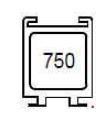
| Number | Ampere rating [A] | Description |
| 750 | 40 | Child safety |
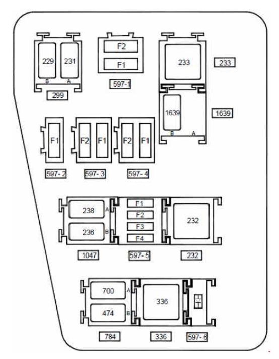
Engine compartment fuse box (K4M690-K4M694)
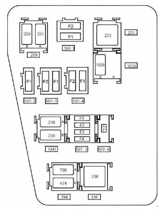
| Number | Ampere rating [A] | Description |
| Fuse board 597- 1 | ||
| F1 | 50 | Anti-lock braking system electric control unit on versions without electronic stability program |
| F2 | 25 | Anti-lock braking system electric control unit on versions without electronic stability program |
| Fuse board 597- 2 | ||
| F1 | 40 | Fuse on air conditioning version: Cooling fan assembly supply via fan assembly high-speed relay or via fan assembly low speed relay on relay board and fan assembly resistor – air conditioning clutch supply via air conditioning clutch relay on board |
| Fuse board 597- 3 | ||
| F1 | 60 | Ignition switch – monolever – supply to fuse F23 on passenger compartment fuse box |
| F2 | 60 | Monolever supply – supply to fuses F29 and F36 on passenger compartment fuse box |
| Fuse board 597- 4 | ||
| F1 | — | — |
| F2 | 25 | F34 fuse supply on passenger compartment fuse box on 4×4 version (four wheel drive) |
| Fuse board 597- 5 | ||
| F1 | 30 | Fuse on standard heating version: cooling fan assembly supply via low speed fan assembly relay on relay board |
| F2 | 25 | Injection locking relay control and supply on relay board – fuel pump relay supply on relay board |
| F3 | — | — |
| F4 | — | — |
| Diode 597- 6 support plate | ||
| Diode | Air conditioning clutch | |
| Relay board 299 | ||
| A | 20 | Front fog lights |
| B | 20 | Horn |
| Unit relay 233 | ||
| 233 | 40 | Cold air blower |
| Relay board 1047 | ||
| A | 20 | Injection locking |
| B | 20 | Fuel pump |
| Relay board 784 | ||
| A | 20 | Low speed fan assembly |
| B | 20 | Air conditioning clutch |
| Unit relay 336 | ||
| 336 | 40 | High speed fan assembly |
| Relay 1639 board on FLEXFUEL version | ||
| A | — | Not in use |
| B | 20 | Additional fuel pump |
Engine compartment fuse box (F4R400-F4R402-F4R403-F4R404-F4R405-F4R408)
| Number | Ampere rating [A] | Description |
| Fuse board 597- 1 | ||
| F1 | 50 | Anti-lock braking system electric control unit on versions without electronic stability program |
| F2 | 25 | Anti-lock braking system electric control unit on versions without electronic stability program |
| Fuse board 597- 2 | ||
| F1 | 40 | Fuse on air conditioning version: cooling fan assembly supply via high speed fan assembly relay or via low speed fan assembly relay on relay board and fan assembly resistor |
| Fuse board 597- 3 | ||
| F1 | 60 | Ignition switch – monolever – supply to fuse F23 on passenger compartment fuse box |
| F2 | 60 | Monolever supply – supply to fuses F29 and F36 on passenger compartment fuse box |
| Fuse board 597- 4 | ||
| F1 | — | — |
| F2 | 25 | F34 fuse supply on passenger compartment fuse box on 4×4 version (four wheel drive) |
| Fuse board 597- 5 | ||
| F1 | 15 | Fuse on air conditioning version: Air conditioning clutch supply via air conditioning clutch relay on board |
| F2 | 25 | Injection locking relay control and supply on relay board – fuel pump relay supply on relay board |
| F3 | — | — |
| F4 | 15 | Automatic gearbox electric control unit (119) with 4-speed automatic gearbox on F4R403 and F4R405 engines |
| Diode 597- 6 support plate | ||
| Diode | Air conditioning clutch | |
| Relay board 299 | ||
| A | 20 | Front fog lights |
| B | 20 | Horn |
| Unit relay 233 | ||
| 233 | 40 | Cold air blower |
| Relay board 1047 | ||
| A | 20 | Injection locking |
| B | 20 | Fuel pump |
| Relay board 784 | ||
| A | 20 | Low speed fan assembly |
| B | 20 | Air conditioning clutch |
| Unit relay 336 | ||
| 336 | 40 | High speed fan assembly |
| Unit relay 232 on automatic gearbox version | ||
| 22 | 40 | Starter |
| Relay 1639 board on FLEXFUEL version | ||
| A | — | — |
| B | 20 | Additional fuel pump |
WARNING: Terminal and harness assignments for individual connectors will vary depending on vehicle equipment level, model, and market.