Isuzu N-Series – fuse box diagram
Year of production:
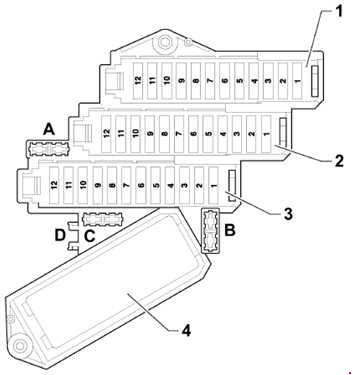
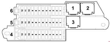
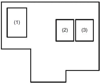
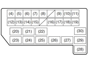
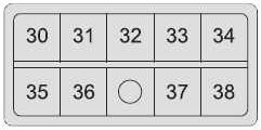
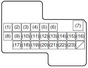
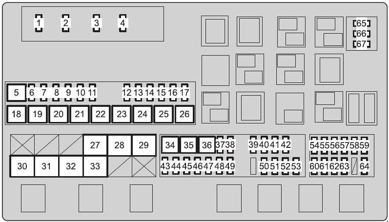
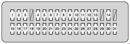
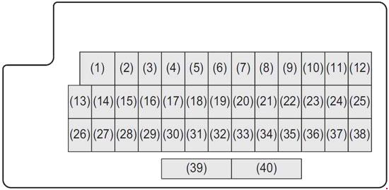
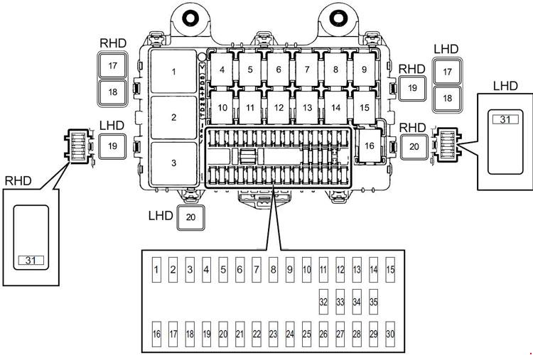
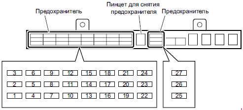
Passenger compartment fuse box (4HG1 engine model (type 1), 4JJ1/4HK1 engine models)
| No. |
Circuit Protected | A |
| 1 | ELEC PTO (BATT) | 20 |
| 2 | RR P/WINDOW | 20 |
| 3 | ROOM LAMP, AUDIO | 15 |
| 4 | DOOR LOCK | 15 |
| 5 | FOG LAMP | 10 |
| 6 | P/WINDOW | 20 |
| 7 | ABS | 10 |
| 8 | WIPER | 15 |
| 9 | H/LAMP LO (LH) | 10 |
| 10 | ECU (BATT) | 10 |
| 11 | H/LAMP LO (RH) | 10 |
| 12 | STOP LAMP | 10 |
| 13 | IGNITION 2 | 15 |
| 14 | H/LAMP HI (LH) | 10 |
| 15 | H/LAMP HI (RH) | 10 |
| 16 | ELEC PTO (KEY ST) | 10 |
| 17 | STARTER | 10 |
| 18 | IGNITION 1 | 15 |
| 19 | SRS | 10 |
| 20 | ECM | 10 |
| 21 | METER | 10 |
| 22 | LAMPS (BATT) | 10 |
| 23 | AUDIO, ACC | 15 |
| 24 | MIRROR | 15 |
| 25 | HORN | 15 |
| 26 | TURN, HAZARD | 15 |
| 27 | TAIL LAMPS | 10 |
| 28 | ILLUMINATIONS | 10 |
| 29 | CORNERING LAMPS, RR FOG LAMP | 10 |
| 30 | BLOWER MOTOR | 20 |
| 31 | SPARE | — |
| 32 | SPARE | — |
| 33 | SPARE | — |
| Relay | ||
| 1 | STOP LAMP | |
| 2 | BLOWER MOTOR | |
| 3 | KEY ON | |
| 4 | 4HG1: BLANK 4JJ1, 4HK1: DOOR LOCK (LOCK) |
|
| 5 | 4HG1: BLANK 4JJ1, 4HK1: REAR FOG LAMP |
|
| 6 | WIPER MAIN | |
| 7 | HORN | |
| 8 | WIPER (HIGH/LOW) | |
| 9 | FOG LAMP | |
| 10 | PTO MAIN | |
| 11 | 4HG1: BLANK 4JJ1, 4HK1: DOOR LOCK (UNLOCK) |
|
| 12 | POWER WINDOW | |
| 13 | HEAD LAMP (LOW) | |
| 14 | 4JJ1, 4HK1, 4HG1: 4WD | |
| 15 | HEAD LAMP (HIGH) | |
| 16 | TAIL LAMP | |
| 17 | 4HG1: EXHAUST BRAKE CUT 4JJ1, 4HK1: PTO SOLENOID, M/T |
|
| 18 | 4HG1: EXHAUST BRAKE 4JJ1, 4HK1: PTO CUT |
|
| 19 | 4JJ1, 4HK1, 4HG1: TRANSFER IGNITION 1 4JJ1, 4HK1: CHARGE (ENGINE RUN) |
|
| 20 | 4HG1: CHARGE (ENGINE RUN) 4JJ1, 4HK1: POWER WINDOW (REAR) |
|
| 21 | 4HG1: PTO SOLENOID, M/T | |
| 22 | 4HG1: PTO CUT | |
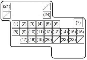
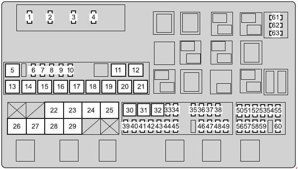
Passenger compartment fuse box (4JB1-T engine model (type 1))
| No. |
Circuit Protected |
A |
| 1 | RR P/WINDOW | 25 |
| 2 | FOG LAMPS | 15 |
| 3 | ROOM LAMP, AUDIO | 10 |
| 4 | DOOR LOCK | 15 |
| 5 | EXHAUST BRAKE | 10 |
| 6 | P/WINDOW | 25 |
| 7 | BACK UP LAMP | 10 |
| 8 | WIPER | 25 |
| 9 | H/LAMP LO (LH) | 10 |
| 10 | LAMPS (BATT) | 10 |
| 11 | H/LAMP LO (RH) | 10 |
| 12 | BRAKE LAMPS | 10 |
| 13 | STARTER | 10 |
| 14 | H/LAMP HI (LH) | 10 |
| 15 | H/LAMP HI (RH) | 10 |
| 16 | BLOWER (IG) | 10 |
| 17 | IGNITION 2 | 10 |
| 18 | IGNITION 1 | 10 |
| 19 | BLANK | — |
| 20 | ECM | 10 |
| 21 | METER | 10 |
| 22 | ECU (BATT) | 10 |
| 23 | MIRROR | 10 |
| 24 | ACCESSORIES, AUDIO | 15 |
| 25 | HORN | 15 |
| 26 | TURN, HAZARD | 15 |
| 27 | TAIL LAM PS | 10 |
| 28 | ILLUMINATIONS | 10 |
| 29 | CORNERING LAMPS | 10 |
| 30 | AIR CONDITIONER | 10 |
| 31 | CIGAR | 20 |
| 32 | SPARE | — |
| 33 | SPARE | — |
| 34 | SPARE | — |
| 35 | SPARE | — |
| Relay | ||
| 1 | STOP LAMP | |
| 2 | FOG LAMP | |
| 3 | KEY ON | |
| 4 | BLANK | |
| 5 | BLANK | |
| 6 | WIPER MAIN | |
| 7 | HORN | |
| 8 | WIPER (HIGH/LOW) | |
| 9 | EXHAUST BRAKE | |
| 10 | RHD: BLANK LHD: POWER WINDOW (REAR) |
|
| 11 | BLANK | |
| 12 | POWER WINDOW | |
| 13 | HEAD LAMP (LOW) | |
| 14 | BLANK | |
| 15 | HEAD LAMP (HIGH) | |
| 16 | TAIL LAMP | |
| 17 | CIGAR | |
| 18 | BLANK | |
| 19 | BLOWER MOTOR | |
| 20 | CHARGE | |
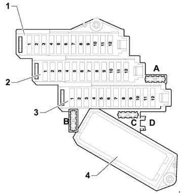
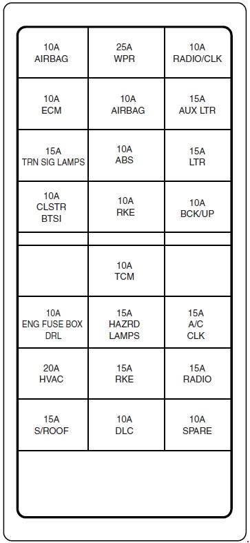
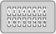
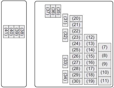
Passenger compartment fuse box (4HG1 engine model (type 2), 4HG1-T engine models)
| No. |
Circuit Protected |
A |
| 1 | LAMPS BATT | 10 |
| 2 | EGR | 10 |
| 3 | ROOM LAMP AUDIO | 15 |
| 4 | DOOR LOCK | 15 |
| 5 | FOG LAMP | 10 |
| 6 | P/WINDOW | 20 |
| 7 | H/LAMP HI (LH) | 10 |
| 8 | H/LAMP HI (RH) | 10 |
| 9 | STOP LAMP | 10 |
| 10 | H/LAMP LO (LH) | 10 |
| 11 | H/LAMP LO (RH) | 10 |
| 12 | BLANK | — |
| 13 | TAIL LAMPS | 10 |
| 14 | CORNERING LAMPS | 10 |
| 15 | IGNITION 2 | 15 |
| 16 | STARTER | 10 |
| 17 | IGNITION 1 | 15 |
| 18 | METER | 10 |
| 19 | ACC AUDIO | 15 |
| 20 | BLANK | — |
| 21 | BLOWER | 20 |
| 22 | HORN | 15 |
| 23 | TURN HAZARD | 15 |
| 24 | WIPER | 15 |
| 25 | SPARE | — |
| 26 | SPARE | — |
| 27 | SPARE | — |
| Relay | ||
| 1 | TAIL LAMP | |
| 2 | HEAD LAMP (HIGH) | |
| 3 | HEAD LAMP (LOW) | |
| 4 | CHARGE (ENGINE RUN) | |
| 5 | STOP LAMP | |
| 6 | BLOWER MOTOR | |
| 7 | KEY ON | |
| 8 | EXHAUST BRAKE | |
| 9 | WIPER MAIN | |
| 10 | WIPER (HIGH/LOW) | |
| 11 | BLANK | |
| 12 | HORN | |
| 13 | A/C COMPRESSOR | |
| 14 | POWER WINDOW | |
| 15 | FOG LAMP | |
Passenger compartment fuse box (4JB1-TC engine model (type 2), 4JB1 engine models)

| No. |
Circuit Protected |
A |
| 1 | BLANK | — |
| 2 | ROOM LAMP AUDIO | 10 |
| 3 | EXH BRAKE | 10 |
| 4 | DOOR LOCK | 15 |
| 5 | FOG LAMP | 15 |
| 6 | P/WINDOW | 25 |
| 7 | H/LAMP HI (LH) | 10 |
| 8 | H/LAMP HI (RH) | 10 |
| 9 | STOP LAMP | 10 |
| 10 | H/LAMP LO (LH) | 10 |
| 11 | H/LAMP LO (RH) | 10 |
| 12 | TAIL LAM PS | 10 |
| 13 | LAMPS BATT | 10 |
| 14 | IGNITION 2 | 10 |
| 15 | STARTER | 10 |
| 16 | ENGINE STOP | 10 |
| 17 | IGNITION 1 | 10 |
| 18 | BACK UP LAMPS | 10 |
| 19 | METER | 10 |
| 20 | ACC AUDIO | 15 |
| 21 | AIR CON | 10 |
| 22 | HORN | 15 |
| 23 | TURN HAZARD | 15 |
| 24 | WIPER | 25 |
| 25 | SPARE | — |
| 26 | SPARE | — |
| 27 | SPARE | — |
| Relay | ||
| 1 | TAIL LAMP | |
| 2 | HEAD LAMP (HIGH) | |
| 3 | HEAD LAMP (LOW) | |
| 4 | POWER WINDOW | |
| 5 | STOP LAMP | |
| 6 | CHARGE (ENGINE RUN) | |
| 7 | KEY ON | |
| 8 | EXHAUST BRAKE | |
| 9 | WIPER MAIN | |
| 10 | WIPER (HIGH/LOW) | |
| 11 | FOG LAMP | |
| 12 | HORN | |
| 13 | BLANK | |
| 14 | BLOWER MOTOR | |
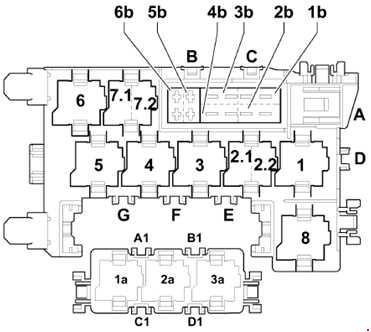
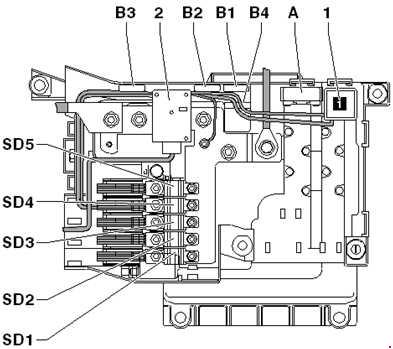
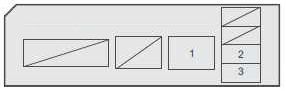
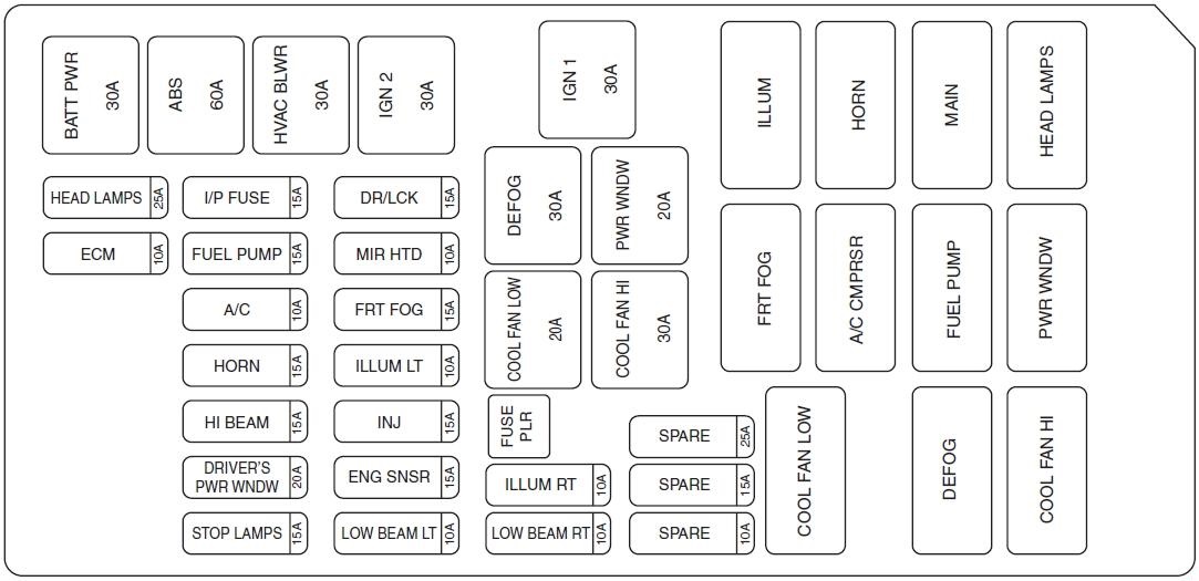
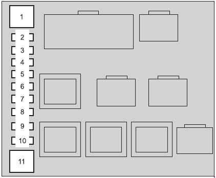
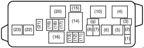
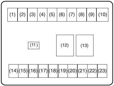
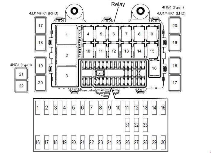
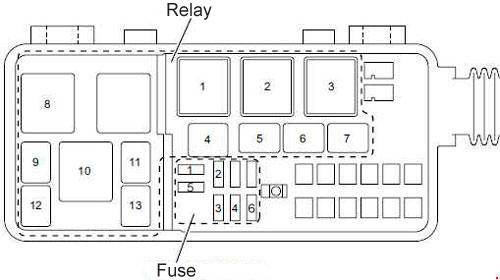
Fuse and Relay Location (Cab Exterior)
| No. |
Circuit Protected |
A |
| 1 | MARKER LAMP 4HG1: Not used |
10 |
| 1 | 4JB1-TC: FUEL HEATER | 15 |
| 2 | ECM MAIN 4JB1-TC, 4HG1: Not used |
10 |
| 3 | BATTERY | 10 |
| 3 | 4JB1-TC: BATTERY | 15 |
| 4 | A/C 4JB1-TC: Not used |
10 |
| 5 | 4HK11,2), 4JJ1: Not used 4JB1-TC: MARKER LAMP 4HG1: FUEL HEATER |
20 |
| 6 | 4HK1, 4JJ1: Not used 4JB1-TC: A/C 4HG1: ENGINE STOP |
15 |
| Relay | ||
| 1 | STARTER | |
| 2 | 4HK1, 4JJ1: ECM 4JB1-TC, 4HG1: Not used |
|
| 3 | GLOW PLUG | |
| 4 | A/C COMPRESSOR | |
| 5 | CONDENSER FAN | |
| 6 | 4HK1, 4JJ1: STARTER CUTOFF 4JB1-TC: EXHAUST BRAKE 4HG1: ENGINE STOP |
|
| 7 | 4HK11), 4JJ1: MARKER LAMP (MODEL WITH REAR FOG LAMP) 4HK12): EXHAUST BRAKE 4JB1-TC, 4HG1: FUEL HEATER |
|
| 8 | GEARSHIFTER | |
| 9 | 4WD (NPS MODEL) | |
| 10 | FUEL HEATER (MODEL WITH FUEL HEATER) | |
| 11 | TRANSFER GEAR CONTROL (NPS MODEL) | |
| 12 | ENGINE RUN> (MODEL WITH FUEL HEATER) | |
| 13 | 4HK12): MARKER LAMP (MODEL WITH REAR FOG LAMP) | |
| 1) 4HK1 engine model (Euro IV emission standards), 4JJ1 engine model 2) 4HK1 engine model (Euro II emission standards or Euro III emission standards) |
||
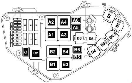
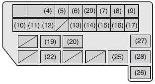
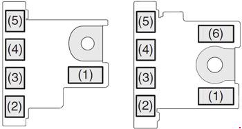
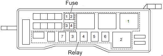
Fuse and Relay Location (Cab Exterior; 4HG1-T, 4JB1, 4JB1-TC (type 2), 4HG1 (type 2))
| No. |
Circuit Protected |
A |
| 1 | 4JB1-TC (type 2), 4JB1: POWER SOURCE | 15 |
| 1 | 4HG1 (type 2), 4HG1-T: ENG STOP | 10 |
| 2 | 4JB1-TC (type 2), 4JB1: FUEL HEATER | 15 |
| 2 | 4HG1 (type 2), 4HG1-T: BAT SPARE | 10 |
| 3 | 4JB1-TC (type 2), 4JB1: A/C | 20 |
| 3 | 4HG1 (type 2), 4HG1-T: FUEL HEATER | 10 |
| 4 | 4JB1-TC (type 2), 4JB1: CONDENSER FAN | 20 |
| 4 | 4HG1 (type 2), 4HG1-T: A/C | 10 |
| Relay | ||
| 1 | GLOW | |
| 2 | STARTER | |
| 3 | 4HG1 (type 2), 4HG1-T: CSD 4JB1-TC (type 2), 4JB1: Not Used |
|
| 4 | FUEL HEATER | |
| 5 | CONDENSER FAN | |
| 6 | EXT BRAKE | |
| 7 | 4HG1 (type 2), 4HG1-T: Not Used 4JB1-TC (type 2), 4JB1: CSD |
|
WARNING: Terminal and harness assignments for individual connectors will vary depending on vehicle equipment level, model, and market.