Audi A6 (C4) (1994 – 1997) – fuse box diagram
Year of production: 1994, 1995, 1996, 1997
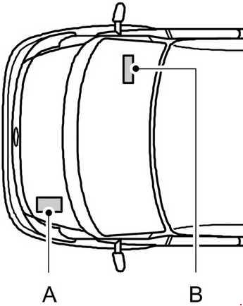
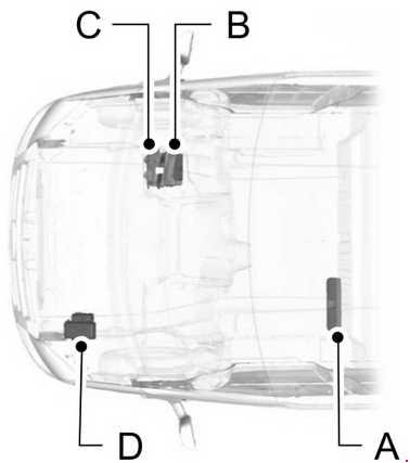
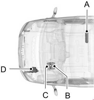
Location
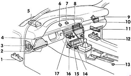
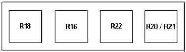
- Auxiliary relay panel II
- Central electric panel with relay holder
- Fuse panel
- Connector station I
- Auxiliary relay panel I
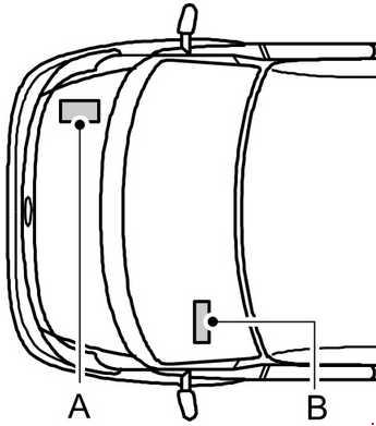
- Emergency flasher relay -J2-
- Radio/parking light warning buzzer -J152-
- Electronic control box
- Board computer range calibration regulator -E46-
- Servotronic control module -J236-
- Connector station II
- Auxiliary relay panel III
- Shift lock warning buzzer -H9-
- Airbag system connector
- A/C control head -E87-
- Airbag triggering unit -J178-
- Connector station III
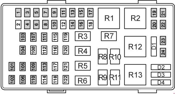
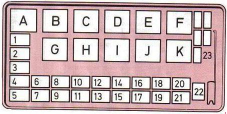
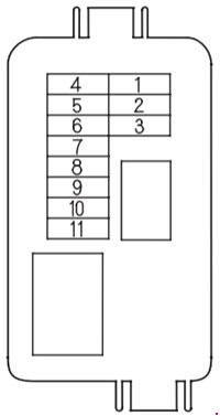
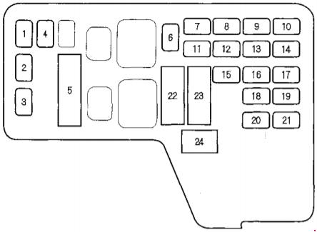
Instrument Panel Fuse Block
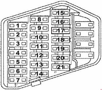
| No. |
Function/component |
A |
| 1 | High Beam Headlight, Right Instrument Cluster |
10 |
| 2 | High Beam Headlight, Lett | 10 |
| 3 | Headlight, Right | 10 |
| 4 | Headlight, Left | 10 |
| 5 | Parking Light, Right Tail Light, Right Brake Light, Right |
5 |
| 6 | Parking Light, Left Tail Light, Left Brake Light, Left |
5 |
| 7 | Engine Compartment Light Glove Compartment Light License Plate Light |
10 |
| 8 | Luggage Compartment Light Footwell Light, Left Footwell Light, Right |
15 |
| 9 | Brake Light Switch Brake Light |
10 |
| 10 | Emergency Flasher Switch Central Locking / Alarm System / Interior Light Delay Control Module |
15 |
| 11 | Fresh Air Blower | 30 |
| 12 | Rear Window Defogger Mirror Heating Elements |
30 |
| 13 | Windshield Wiper Motor Washer Nozzle Heaters Turn Signals |
25 |
| 14 | Seat Belt Warning Light Lamp Control Module, Rear |
15 |
| 15 | Instrument Cluster Mirror Adjustment Switch |
5 |
| 16 | Rear Fog Light | 15 |
| 17 | FP (Fuel Pump) | 15 |
| 18 | Rear Window Wiper Motor (Wagon) | 15 |
| 19 | Dual Horn Relay Data Link Connector |
25 |
| 20 | Cruise Control Switch | 5 |
| 21 | ABS | 15 |
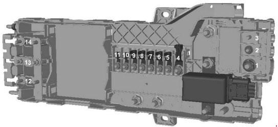
Auxiliary relay panel I
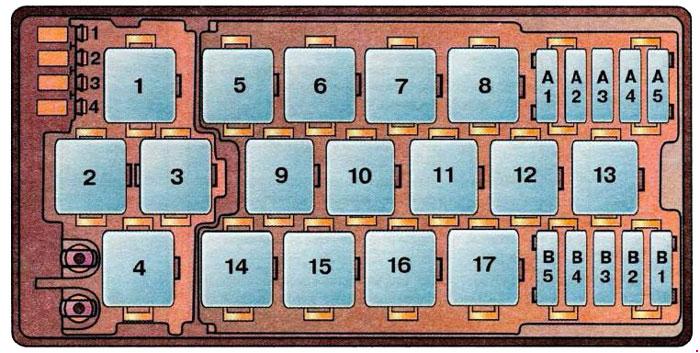
| No. |
Function/component |
| 1 | Control cooling fan with engine off Relay |
| 2 | Coolant FC (Fan Control) Relay |
| 3 | Fog Light Relay |
| 4 | Intensive Washer Pump Relay |
| 5 | Not used |
| 6 | Intensive Washer Pump Relay |
| 7 | Daytime Running Lights Relay (Switch-On), J90 (Canada Only) |
| 8 | Selector Lever Light Relay. J307 |
| 9 | A/C Clutch Relay, J44 |
| 10 | A/C Clutch Control Module, J153 |
| 11 | Rear Window / Wiper Washer Relay, J31 |
| 12 | Not used |
| 13 | Speaker Power Supply Relay, J225 |
| 14 | Lamp Control Module, Rear, J124 |
| 15 | Lamp Control Module, Rear, J124 |
| 16 | Control Module Alarm Horn, J31 |
| 17 | A/C Relay, J32 |
| Circuit breakers | |
| A1 | Automatic Window Closing Circuit Breaker (S99) |
| A2 | Central Locking System Motor Circuit Breaker (S85) |
| A3 | Power Window Circuit Breaker (S43) |
| A4 | Radio Circuit Breaker (S84) |
| A5 | Heated Seat Circuit Breaker (S79) |
| B1 | Memory Seat Adjusting Circuit Breaker (S44) |
| B2 | Power Seat Circuit Breaker (S80) |
| B3 | Door Lock Heating Element Circuit Breaker (S86) |
| B4 | Not used |
| B5 | Sunroof Circuit Breaker (S83) |
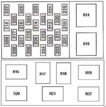
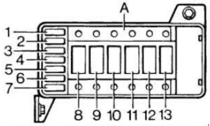
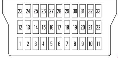
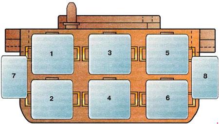
Auxiliary relay panel II

| No. | Function/component |
| 1 | Power Window Control Module, J139 |
| 2 | Power Window Control Module, J139 |
| 3 | Automatic Window Closing Relay, J261 |
| 4 | ABS Combi Relay, J156 |
| 5 | Shift Lock Control Module, J221 |
| 6 | Automatic Transmission Relay, J60 |
| 7 | Electronic Damping Control Module Fuse, S31 |
| 8 | Coolant Fan Fuse, S42 |
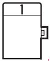
Auxiliary relay panel III
| No. | Function/component |
| 1 | Not used |
| 2 | Airbag Control Light Relay, J312 |
| 3 | Not used |
| 4 | Not used |
| 5 | Switch unit for water pump, relay fan stage 1 |
| 6 | Not used |
| 7 | Oxygen sensor heater |
| 8 | Pump air in exhaust manifold |
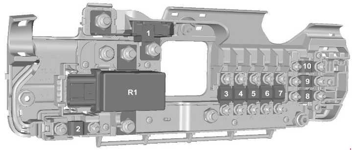
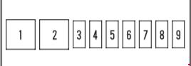
Central electric panel with relay holder
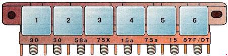
| No. | Function/component |
| 1 | Load Reduction Relay, J59 |
| 2 | Dual Horn Relay, J4 |
| 3 | Headlight Washer System Relay, J39 |
| 4 | Back-Up Light Relay (Manual Transmission), J219 PNP (Park/Neutral Position) Relay (Automatic Transmission), J226 |
| 5 | Washer / Wiper Intermittent Relay, J31 |
| 6 | FP (Fuel Pump) Relay, J17 |
WARNING: Terminal and harness assignments for individual connectors will vary depending on vehicle equipment level, model, and market.