Mercedes-Benz GLC-Class x253 – fuse box diagram
Year of production:
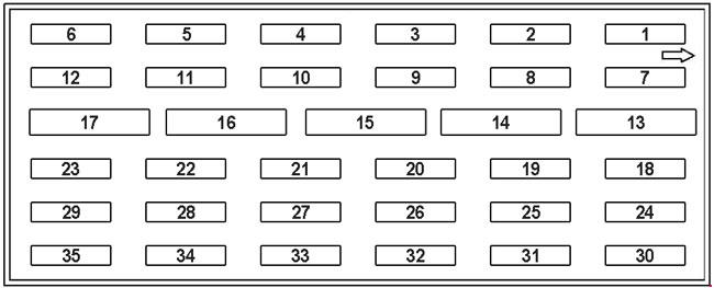
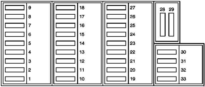
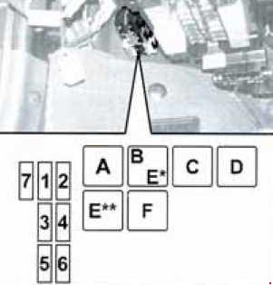
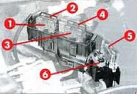
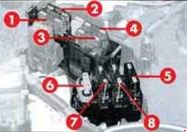
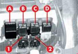
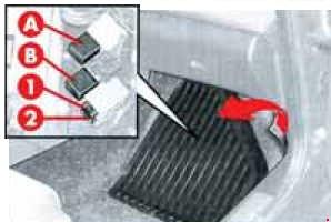
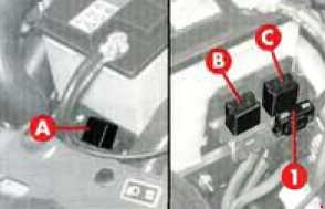
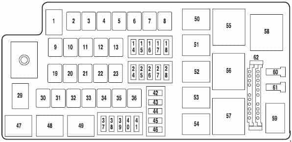
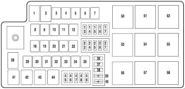
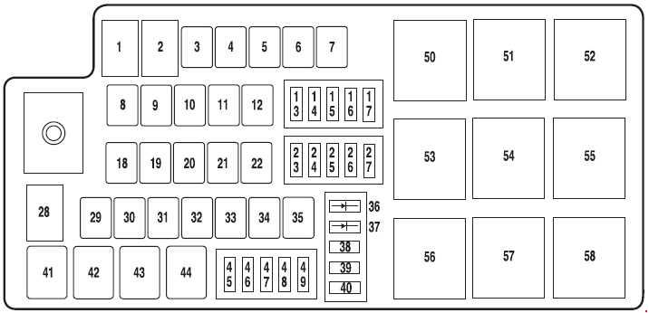
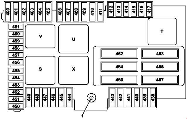
Fuse Box in the Trunk
Variant 1
Variant 2
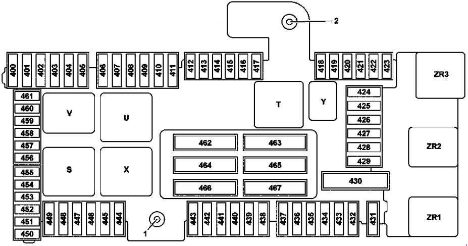
1 – Terminal 30 “E1” feed
2 – Terminal 30g “E2” feed
| Number | A | Description |
| 400 | 25 | BlueTEC: AdBlue® control unit |
| 401 | 15 | BlueTEC: AdBlue® control unit |
| 402 | 20 | BlueTEC: AdBlue® control unit |
| 403 | 30 | Valid up to 30.11.2015: Front passenger seat partially electric seat adjustment switch |
| 25 | Valid as of 01.12.2015: Front passenger seat partially electric seat adjustment switch | |
| 404 | 30 | Valid up to 30.11.2015: Driver seat partially electric seat adjustment switch |
| 25 | Valid as of 01.12.2015: Driver seat partially electric seat adjustment switch | |
| 405 | — | Spare |
| 406 | 30 | Left front door control unit |
| 407 | — | Spare |
| 408 | 30 | Right rear door control unit |
| 409 | — | Spare |
| 410 | 5 | Stationary heater radio remote control receiver Antenna changeover switch for telephone and stationary heater |
| 411 | 30 | Left front reversible emergency tensioning retractor |
| 412 | 7,5 | Hybrid: Battery management system control unit |
| 413 | 5 | Trunk lid control control unit |
| 414 | 5 | Tuner unit |
| 415 | 5 | Camera cover control unit Perfume atomizer generator |
| 416 | 7,5 | Cellular telephone system antenna amplifier/compensator Mobile phone contact plate |
| 417 | 5 | 360° camera control unit Reversing camera |
| 418 | 5 | Rear seat heater control unit AIRSCARF control unit |
| 419 | 5 | Front passenger seat lumbar support adjustment control unit |
| 420 | 5 | Driver seat lumbar support adjustment control unit |
| 421 | — | Spare |
| 422 | — | Spare |
| 423 | 5 | Sound system amplifier control unit |
| 424 | 15 | AIR BODY CONTROL Plus control unit Valid for engine 276: Engine sound control unit |
| 425 | — | Spare |
| 426 | — | Spare |
| 427 | — | Spare |
| 428 | — | Spare |
| 429 | — | Spare |
| 430 | — | Spare |
| 431 | 25 | Special-purpose vehicle multifunction control unit |
| 432 | 25 | Special-purpose vehicle multifunction control unit |
| 433 | 20 | Trailer recognition control unit |
| 434 | 30 | Trailer recognition control unit |
| 435 | 25 | Trailer recognition control unit |
| 436 | 15 | Trailer recognition control unit |
| 437 | 25 | Trailer recognition control unit |
| 438 | 30 | DC/AC converter control unit |
| 439 | — | Spare |
| 440 | 30 | Rear seat heater control unit AIRSCARF control unit |
| 441 | 30 | AIRSCARF control unit |
| 442 | 25 | Fuel system control unit |
| 443 | 30 | Right front reversible emergency tensioning retractor |
| 444 | 15 | Tablet PC electrical connector |
| 445 | 15 | Luggage compartment socket |
| 446 | 15 | Front cigarette lighter with ashtray illumination Vehicle interior power outlet |
| 447 | 15 | Right rear center console socket 12V |
| 448 | 10 | Valid for transmission 722, 725: Park pawl capacitor |
| 449 | 5 | Valid for engine 626: Fuel filter element with integrated heater Hybrid: Sound generator |
| 450 | 5 | Rear SAM control unit |
| 451 | 5 | Fuel system control unit BlueTEC: AdBlue® control unit |
| 452 | 5 | Integrated outer right rear bumper radar sensor Integrated outer left rear bumper radar sensor Center rear bumper radar sensor Outer right rear bumper radar sensor Outer left rear bumper radar sensor |
| 453 | 5 | Left front bumper radar sensor Right front bumper radar sensor COLLISION PREVENTION ASSIST controller unit |
| 454 | 7,5 | Valid for transmission 722: Fully integrated transmission control unit |
| 5 | BlueTEC: AdBlue® control unit | |
| 455 | 5 | DC/AC converter control unit |
| 456 | 5 | Front long-range radar sensor DISTRONIC electric controller unit |
| 457 | 5 | Hybrid: Power electronics control unit DC/DC converter control unit Power electronics control unit |
| 458 | 5 | Rear switching module |
| 459 | 5 | Hybrid: Charger |
| 460 | 10 | KEYLESS-GO control unit |
| 461 | 5 | FM 1, AM, CL [ZV] and KEYLESS-GO antenna amplifier |
| 462 | 40 | Sound system amplifier control unit |
| 463 | 30 | Rear window heater via rear window interference suppression capacitor |
| 464 | 40 | Trunk lid control control unit Liftgate control control unit |
| 465 | 40 | Rear SAM control unit |
| 466 | 40 | Rear SAM control unit |
| 467 | 40 | Valid for engine 626: Fuel filter element with integrated heater |
| Relay |
||
| S | Vehicle interior circuit 15 relay |
|
| T | Rear window heater relay | |
| U | 2nd seat row cup holder and sockets relay | |
| V | BlueTEC: AdBlue® relay | |
| X | 1 st seat row/trunk refrigerator box and sockets relay | |
| Y | Spare relay | |
| ZR1 | Valid for engine 626: Fuel filter heater relay | |
| ZR2 | Reserve relay | |
| ZR3 | Reserve relay | |
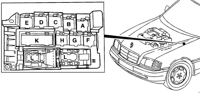
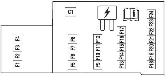
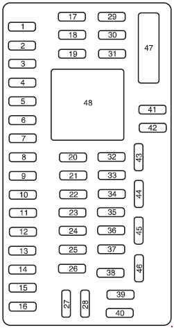
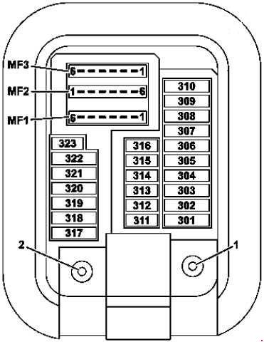
Fuse Box in the Front-Passenger Footwell
| Number | A | Description |
| 301 | 5 | Hybrid: Pyrofuse via high-voltage disconnect device |
| 302 | 30 | Right front door control unit |
| 303 | 30 | Left rear door control unit |
| 304 | 20 | Valid for transmission 722: Intelligent servo module for DIRECT SELECT (A80) |
| 305 | 30 | Driver seat control unit Driver seat heater control unit Front seat heater control unit |
| 306 | 30 | Front passenger seat control unit Front passenger seat heater control unit Front seat heater control unit |
| 307 | — | Spare |
| 308 | 30 | USA version: Electric Brake Control electrical connector |
| 309 | 10 | Emergency call system control unit |
| 5 | HERMES control unit Telematics services communications module |
|
| 310 | — | Spare |
| 311 | 10 | Booster blower electronic blower regulator |
| 312 | 10 | Overhead control panel control unit |
| 313 | 10 | Hybrid: DC/DC converter control unit |
| 314 | — | Spare |
| 315 | 5 | Powertrain control unit Valid for diesel engine: CDI control unit Valid for gasoline engine: ME-SFI control unit |
| 316 | 7,5 | Supplemental Restraint System control unit |
| 317 | 7,5 | Panoramic sliding sunroof control module Sliding roof control module |
| 318 | 20 | Stationary heater control unit |
| 319 | 5 | Hybrid: High-voltage PTC heater |
| 320 | 15 | AIR BODY CONTROL control unit |
| 321 | 5 | Japan version: Dedicated Short-Range Communications control unit |
| 322 | 20 | Head unit |
| 323 | 5 | Parking system control unit |
| MF1/1 | 7,5 | Audio/COMAND display Audio equipment fan motor |
| MF1/2 | 7,5 | Stereo multifunction camera Mono multifunction camera |
| MF1/3 | 7,5 | Rain/light sensor with additional functions Overhead control panel control unit |
| MF1/4 | 7,5 | Driver seat control unit Driver seat heater control unit Front seat heater control unit |
| MF1/5 | 7,5 | Front passenger seat control unit Front passenger seat heater control unit Front seat heater control unit |
| MF1/6 | 7,5 | Steering column tube module control unit |
| MF2/1 | 5 | Left front reversible emergency tensioning retractor |
| MF2/2 | 5 | Audio/COMAND control panel Touchpad |
| MF2/3 | 5 | Right front reversible emergency tensioning retractor |
| MF2/4 | 5 | Heads-up display |
| MF2/5 | 5 | Multimedia connection unit |
| MF2/6 | 5 | Hybrid: Electrical refrigerant compressor |
| MF3/1 | 5 | Feedback line, terminal 30g, front SAM control unit |
| MF3/2 | 5 | Radar sensors control unit |
| MF3/3 | — | Spare |
| MF3/4 | 5 | Driver side instrument panel button group |
| MF3/5 | 5 | Rear air conditioning operating unit |
| MF3/6 | 5 | Rear air conditioning operating unit |
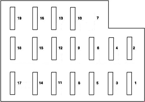
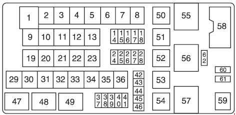
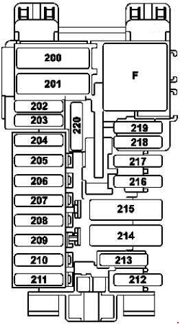
Dashboard Fuse Box
| Number | A | Description |
| 200 | 50 | Front SAM control unit |
| 201 | 40 | Front SAM control unit |
| 202 | 5 | Alarm siren |
| 203 | 20 | Valid with transmission 716: Electric steering lock control unit |
| 204 | 5 | Diagnostic connector |
| 205 | 7,5 | Electronic ignition lock control unit |
| 206 | 5 | Analog clock |
| 207 | 15 | Climate control control unit |
| 208 | 7,5 | Instrument cluster |
| 209 | 5 | Climate control operating unit Upper control panel control unit |
| 210 | 10 | Steering column tube module control unit |
| 211 | 25 | Spare |
| 212 | 5 | Spare |
| 213 | 5 | Electronic Stability Program control unit |
| 214 | 30 | Spare |
| 215 | — | Spare |
| 216 | 7,5 | Glove compartment lamp |
| 217 | 5 | Japan version: Dedicated Short-Range Communications control unit |
| 218 | 7,5 | Supplemental Restraint System control unit |
| 219 | 5 | Weight sensing system (WSS) control unit |
| 220 | — | Spare |
| Relay | ||
| F | Relay, circuit 15R | |
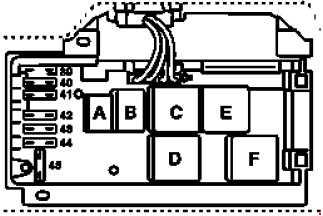
Fuse Box in the Engine Compartment
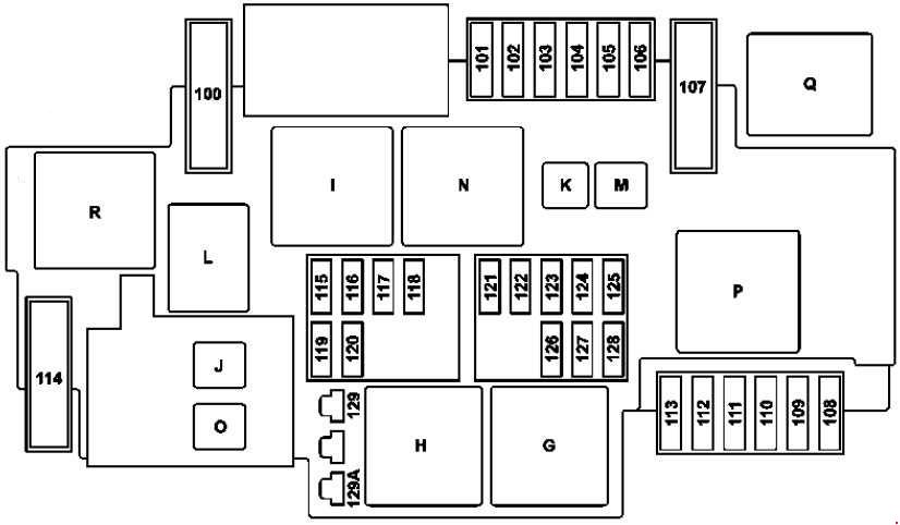
| Number | A | Description |
| 100 | 40 | Hybrid: Vacuum pump |
| 101 | 15 | Connector sleeve, circuit 87/2 |
| 102 | 20 | Connector sleeve, circuit 87/1 |
| 103 | 15 | Connector sleeve, circuit 87/4 |
| 104 | 15 | Connector sleeve, circuit 87/3 |
| 105 | 15 | Valid for transmission 722.9 (except 722.930): Automatic transmission fluid auxiliary oil pump control unit |
| 106 | — | Spare |
| 107 | 60 | Valid with engine 274.9: Electric coolant pump |
| 108 | 20 | Static LED headlamp: Right front lamp unit High performance LED, Dynamic LED headlamp: Left front lamp unit Right front lamp unit |
| 109 | 30 | Wiper motor |
| 110 | 20 | Static LED headlamp: Left front lamp unit High performance LED, Dynamic LED headlamp: Left front lamp unit Right front lamp unit |
| 111 | 30 | Starter |
| 112 | 15 | Hybrid: Accelerator pedal sensor |
| 113 | — | Spare |
| 114 | 40 | AIR BODY CONTROL compressor |
| 115 | 15 | Left horn and right horn |
| 116 | — | Spare |
| 117 | — | Spare |
| 118 | 5 | Hybrid: Electronic Stability Program control unit |
| 119 | 15 | Circuit 87 C2 connector sleeve |
| 120 | 5 | Circuit 87 C1 connector sleeve |
| 121 | 5 | Electronic Stability Program control unit |
| 122 | 5 | CPC relay |
| 123 | — | Spare |
| 124 | — | Spare |
| 125 | 5 | Front SAM control unit |
| 126 | 5 | Powertrain control unit Valid for diesel engine: CDI control unit Valid for gasoline engine: ME-SFI control unit |
| 127 | 5 | Hybrid: Voltage dip limiter |
| 128 | 5 | Left front lamp unit and exterior lights switch |
| 129 | 30 | Hybrid: Starter circuit 50 relay |
| 129A | 30 | Hybrid: Starter circuit 50 relay |
| Relay |
||
| G | Engine compartment circuit 15 relay |
|
| H | Starter circuit 50 relay | |
| I | Hybrid: Vacuum pump relay (+) | |
| J | CPC relay | |
| K | Valid for transmission 722.9 (except 722.930): Oil pump relay | |
| L | Horn relay | |
| M | Wiper park position heater relay | |
| N | Circuit 87M relay | |
| O | Hybrid: Starter circuit 15 relay | |
| P | Valid with engine 274.9: Coolant pump relay | |
| Q | Hybrid: Vacuum pump relay (-) | |
| R | AIR BODY CONTROL relay | |
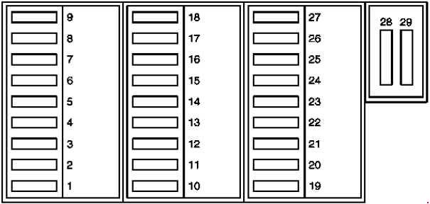
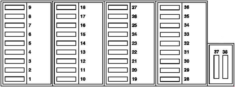
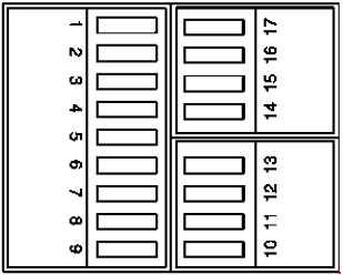
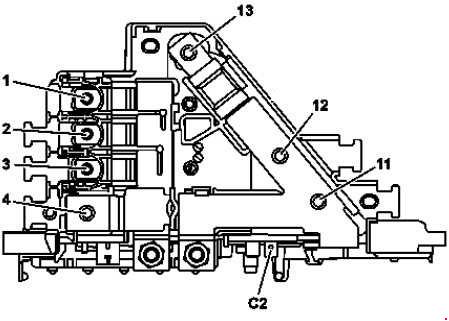
Prefuse Box in Engine Compartment
Variant 1
Variant 2
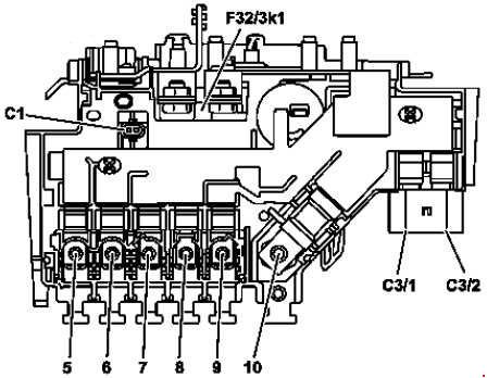
F32/3k1 – Decoupling relay
| Number | A | Description |
| 1 | — | Spare |
| 2 | 100 | Valid for diesel engine: Glow output stage |
| 3 | 60 | Engine fuse and relay module |
| 4 | — | On-board electrical system battery connection |
| 5 | 150 | Engine fuse and relay module |
| 6 | 125 | Left fuse and relay module |
| 7 | 80 | Fan motor (600 W / 850 W) |
| 8 | 125 | Electrical power steering control unit |
| 9 | 150 | Fan motor (1000 W) |
| 10 | 200 | Vehicle interior prefuse box |
| 11 | — | Spare |
| 12 | — | Hybrid: Power electronics control unit With engine 651.9 and USA version: Catalytic converter heater control unit |
| 13 | 400 | Alternator |
| C1 | — | Hybrid: Decoupling relay |
| C2 | — | Hybrid: Circuit 31 |
| C3/1 | 40 | Electronic Stability Program control unit |
| C3/2 | 60 | Electronic Stability Program control unit |
Interior prefuse box
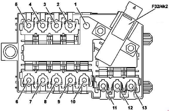
F32/4k2 – Quiescent current cutout relay
| Number | A | Description |
| 1 | — | Engine compartment prefuse box |
| 2 | 150 | Hybrid: Additional battery relay for ECO start/stop function |
| 3 | 40 | Blower regulator |
| 4 | — | Spare |
| 5 | 150 | Valid for diesel engine: PTC heater booster |
| 6 | 80 | Right A-pillar fuse box |
| 7 | 150 | Rear fuse and relay module |
| 8 | — | Spare |
| 9 | — | Spare |
| 10 | 60 | Valid for transmission 725 (except GLC 350 e 4Matic): Fully integrated transmission control unit |
| 100 | GLC 350 e 4Matic: Fully integrated transmission control unit | |
| 11 | — | Spare |
| 12 | 40 | Rear fuse and relay module |
| 13 | 50 | Right A-pillar fuse box |
WARNING: Terminal and harness assignments for individual connectors will vary depending on vehicle equipment level, model, and market.