Vauxhall Vivaro (2001 – 2014) – fuse box diagram
Year of production: 2001, 2002, 2003, 2004, 2005, 2006, 2007, 2008, 2009, 2010, 2011, 2012, 2013, 2014
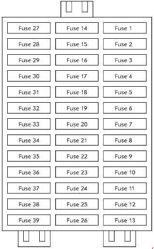
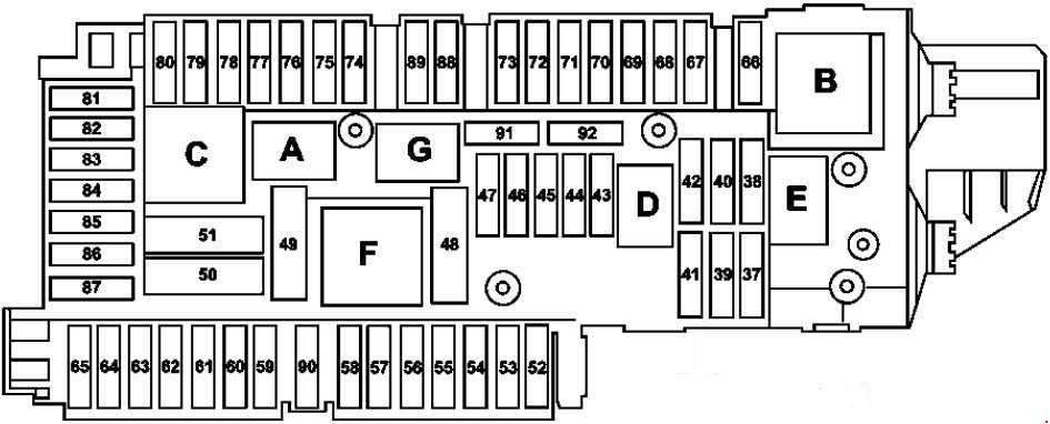
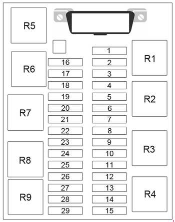
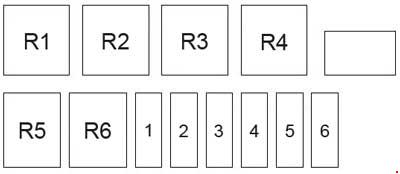
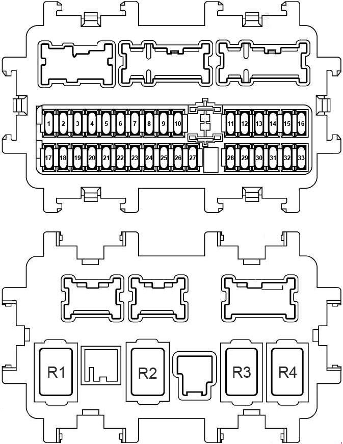
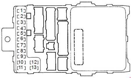
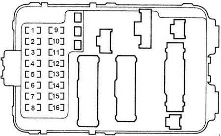
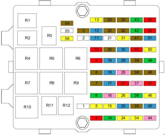
The Instrument Panel Fuse Panel

| Number | Description |
| 1 | — |
| 2 | Radio |
| 3 | — |
| 4 | — |
| 5 | — |
| 6 | — |
| 7 | AC, rear |
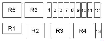
| 8 | — |
| 9 | Fog lamps |
| 10 | Central locking |
| 11 | Interior illumination |
| 12 | Diagnostic plug, immobiliser |
| 13 | Rear screen heating |
| 14 | Rear screen wiper/washer system |
| 15 | Screen wipers |
| 16 | Brake light |
| 17 | ABS |
| 18 | — |
| 19 | Window winders |
| 20 | Window winders |
| 21 | Seat heating |
| 22 | — |
| 23 | — |
| 24 | Radio |
| 25 | Heating |
| 26 | Accessories |
| 27 | High beam, left |
| 28 | High beam, right |
| 29 | Low beam, left |
| 30 | Low beam, right |
| 31 | Tail lamp, left |
| 32 | Tail lamp, right |
| 33 | Rear fog lamp |
| 34 | Horn |
| 35 | Mirror heating |
| 36 | Windscreen heating control |
| 37 | — |
| 38 | — |
| 39 | — |
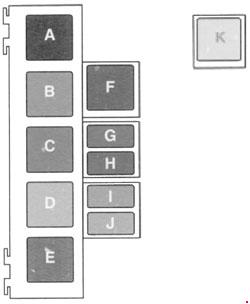
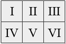
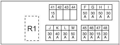
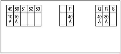
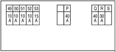
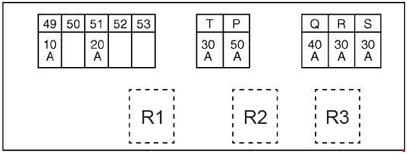
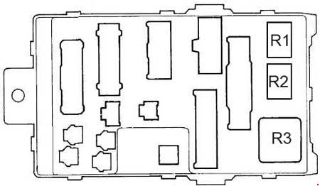
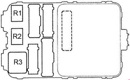
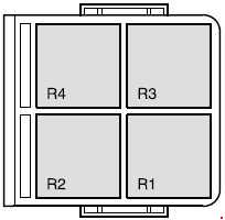
Relay Box

| Number | Relay |
| A | Relay for the rear screen heating |
| B | Time-out for rear screen wipers |
| C | Relay for the rear screen wipers |
| D | Relay + after-contact |
| E | AC tripping relay |
| F | Relay for the heatable windscreen |
| G | Relay for the fog lamps |
| H | “Headlight” relay for low beam |
| I | “Headlight” relay for parking lights |
| J | “Headlight” main relay |
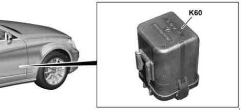
| K | Relay for the electronic thermostat |
The relay for the electronic thermostat is installed on the left-hand side of the air mixer and distributor.
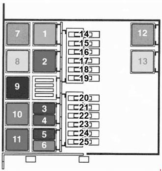
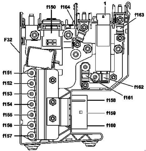
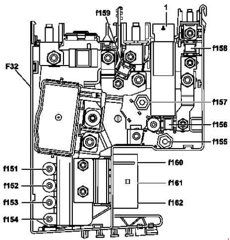
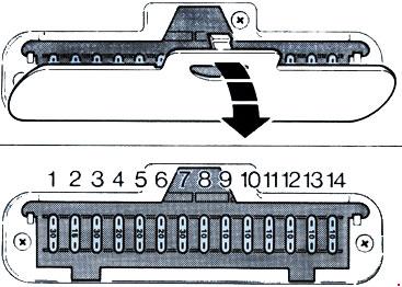
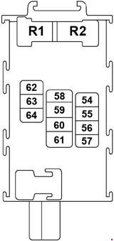
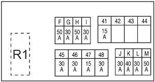
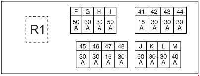
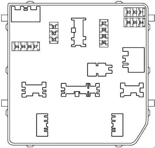
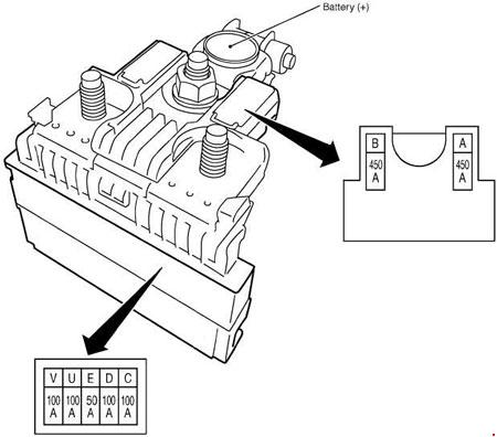
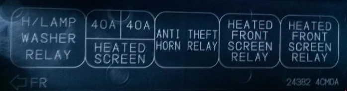
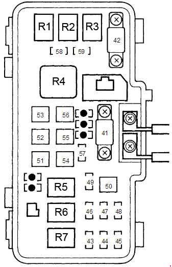
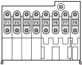
Fuse Box in The Engine Compartment

| Number | A | Relay |
| 14 | — | — |
| 15 | — | — |
| 16 | 40 | AC |
| 17 | 50 | Windscreen heating |
| 18 | 50 | Windscreen heating |
| 19 | 60 | PDB |
| 20 | 60 | ABS |
| 21 | 60 | PDB |
| 22 | 60 | PDB |
| 23 | 50 | Radiator fan |
| 60 | ||
| 70 | ||
| 24 | 50 | Warning autofuse |
| 60 | ||
| 25 | 70 | Pre-heating |
| Relay | ||
| 1 | Auxiliary heater: 2 or 3 add-on heater Diesel: Parking heater relay |
|
| 2 | Diesel: Relay for fuel injection computer Petrol: Injection interrupt |
|
| 3 | Diesel pump relay | |
| 4 | Fuel pump/diesel pre-heating relay | |
| 5 | Diesel parking heater: Relay for fan unit, second speed level | |
| 6 | Coupling relay: AC compressor | |
| 7 | 1 add-on heater (thermo-plunger) relay | |
| 8 | 2 or 3 add-on heater (thermo-plungers) Petrol: Parking heater relay |
|
| 9 | Diesel: Fan unit Diesel: Relay for second speed level with AC Petrol: First speed level with AC |
|
| 10 | Petrol: Fan unit Diesel: Relay for first speed level of the fan with AC Petrol: Second speed level with AC |
|
| 11 | — | |
| 12 | Relay for heatable windscreen. | |
| 13 | Relay for heatable windscreen. | |
In the diesel version the vehicle is either equipped with an auxiliary heater or with a parking heater.
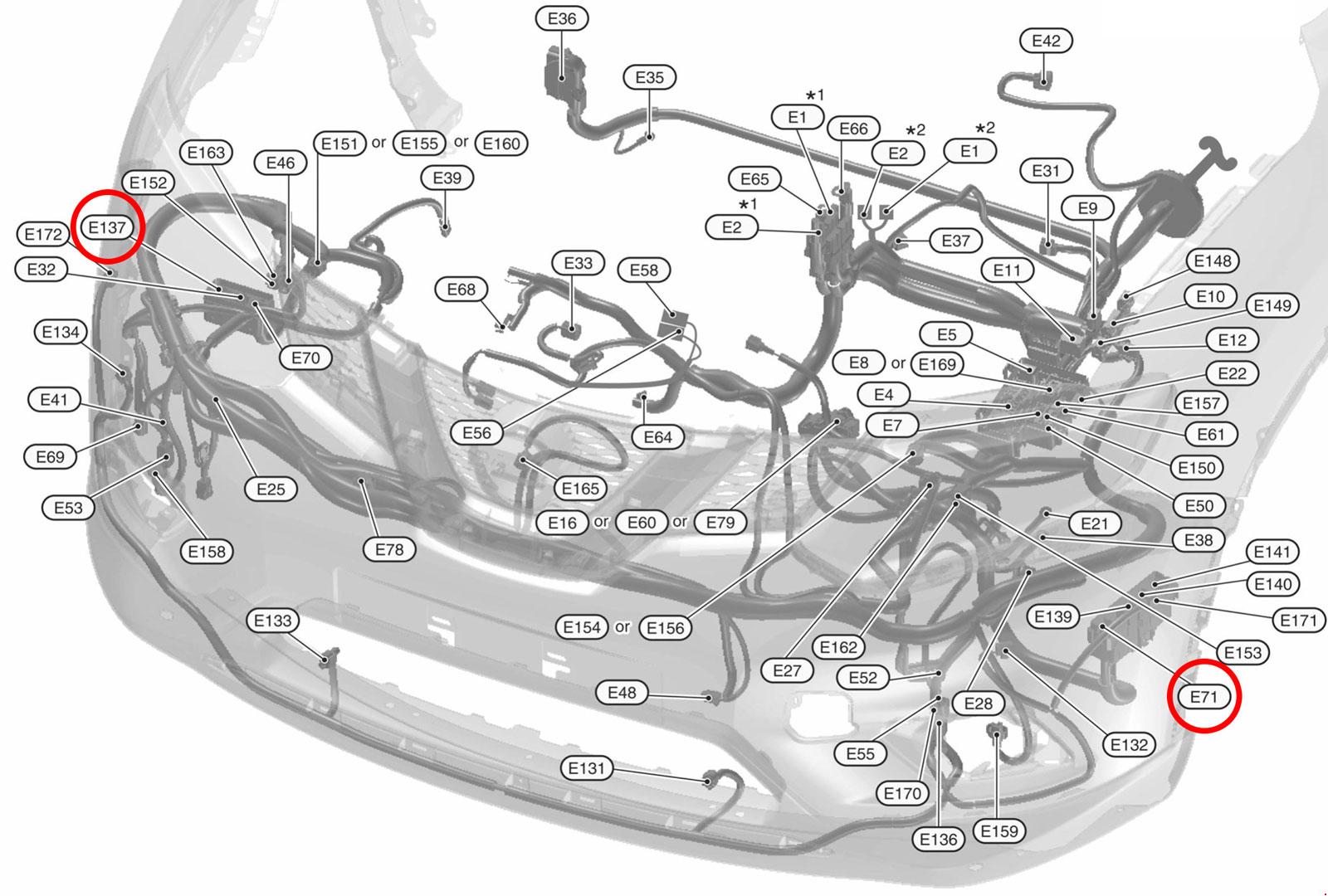
WARNING: Terminal and harness assignments for individual connectors will vary depending on vehicle equipment level, model, and market.