Ford Ka (2008 – 2016) – fuse box diagram
Year of production: 2008, 2009, 2010, 2011, 2012, 2013, 2014, 2015, 2016
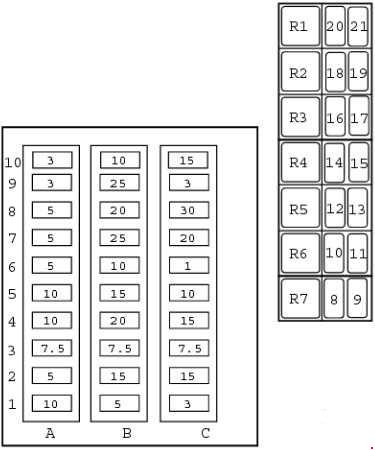
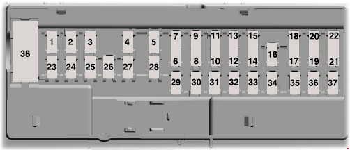
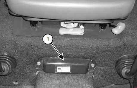
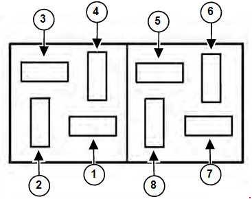
Passenger Compartment Fuse Box
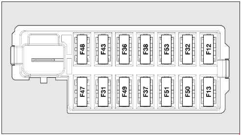
| Number | Ampers | Protected circuit |
| F12 | 7,5 | Right dipped beam power supply |
| F13 | 7,5 | Left dipped headlight and headlight alignment control unit power supply |
| F31 | 5 | Remote switch coils on fuse box in engine compartment (INT/A) |
| F32 | 7,5 | Front and rear roof lights, boot and puddle lights |
| F36 | 10 | Diagnosis socket, radio, climate control, EOBD |
| F37 | 5 | Brake light switch, instrument panel node |
| F38 | 20 | Door central locking |
| F43 | 15 | Windscreen/rear window washer pump |
| F47 | 20 | Driver’s side electric windows |
| F48 | 20 | Passenger side electric window |
| F49 | 5 | Parking sensor, backlighting switches, electric mirrors |
| F50 | 7,5 | Airbag Control Unit |
| F51 | 7,5 | Radio switch, convergence, climate control, brake lights, clutch |
| F53 | 5 | Instrument panel node |
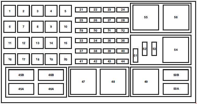
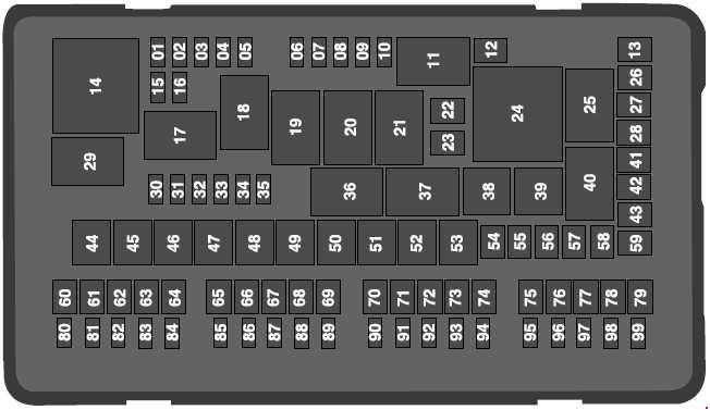
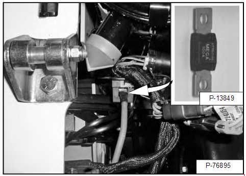
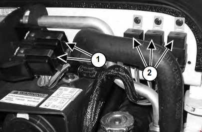
Engine Compartment Fuse Box
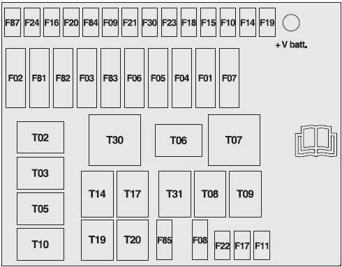
| Number | Ampers | Protected circuit |
| F01 | 60 | Body computer control unit |
| F02 | 20 | Subwoofer, hi-fi audio amplifier |
| F03 | 20 | Ignition switch |
| F04 | 40 | ABS control unit (pump power supply) |
| F05 | 70 | EPS |
| F06 | 20 | Single-speed engine cooling fan |
| 30 | Single-speed engine cooling fan, low speed engine cooling fan | |
| F07 | 40 | High-speed engine cooling fan |
| F08 | 30 | Climate control system fan |
| F09 | 30 | Trailer |
| F10 | 15 | Horns |
| F11 | 10 | Engine control system (secondary loads) |
| F14 | 15 | Main headlights |
| F15 | 15 | Heated seats Sun roof motor |
| F16 | 7,5 | +15 Engine control unit |
| F17 | 10 | Engine control unit |
| F18 | 7,5 | Engine control unit (1.2L Duratec) Engine control unit, relay coil (1.3L Duratorq) |
| F19 | 7,5 | Conditioner compressor |
| F20 | 30 | Heated rear window, mirror demisters |
| F21 | 15 | Fuel pump |
| F22 | 15 | Ignition coil, injectors (1.2L Duratec) |
| 20 | Engine control unit (1.3L Duratorq) | |
| F23 | 20 | ABS control unit (Control unit power supply + Solenoids) |
| Ff24 | 7,5 | +15 ABS control unit (pump power supply), EPS, yaw sensor |
| F30 | 15 | Fog headlights |
| F81 | 50 | Glow plug control unit (1.3L Duratorq) |
| F82 | — | — |
| F83 | 50 | Heated windscreen |
| F84 | — | — |
| F85 | 15 | Front socket (with or without cigar lighter plug) |
| F87 | 7,5 | +15 for reversing lights, debimeter, presence of water in diesel sensor, relay coils T02, T05, T14 and T19 |
WARNING: Terminal and harness assignments for individual connectors will vary depending on vehicle equipment level, model, and market.