Peugeot 205 (1995 – 1998) – fuse box diagram
Year of production: 1995, 1996, 1997, 1998
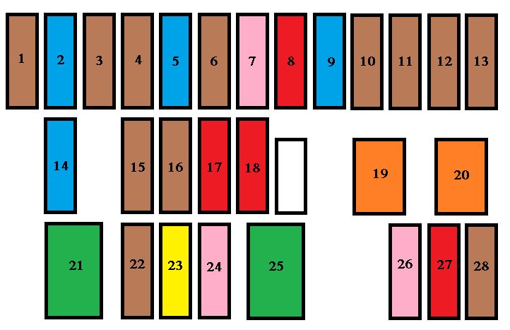
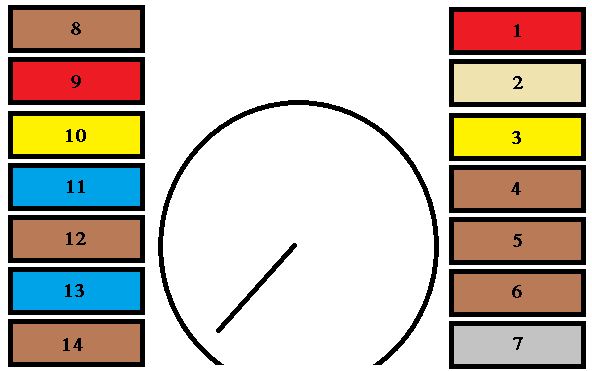
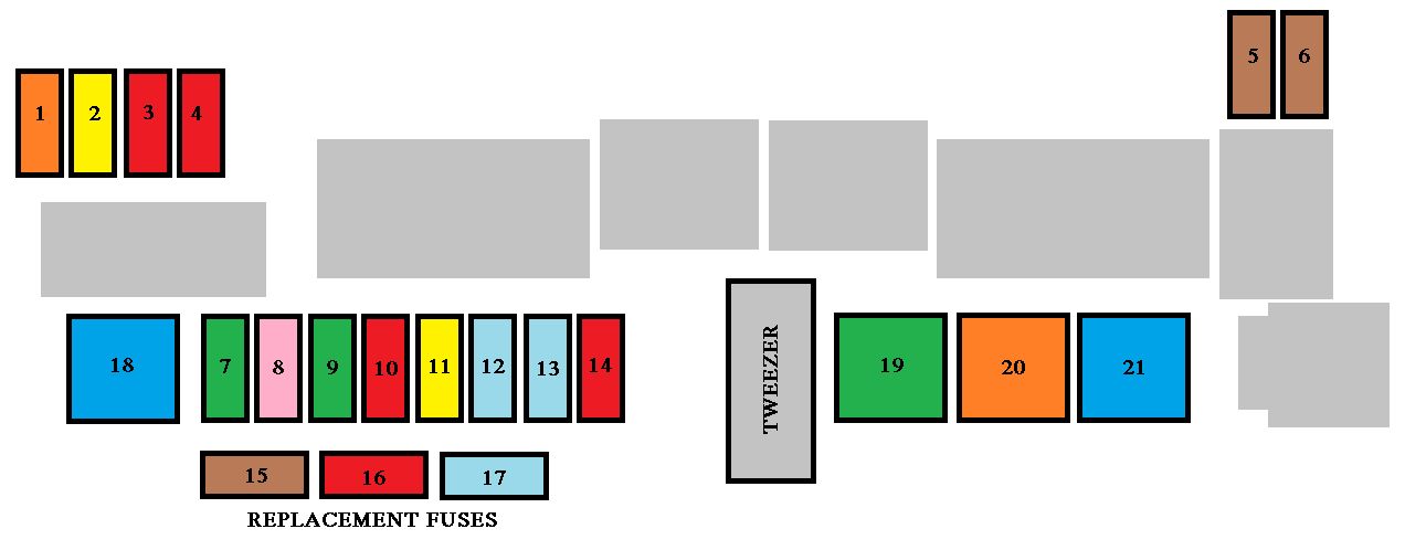
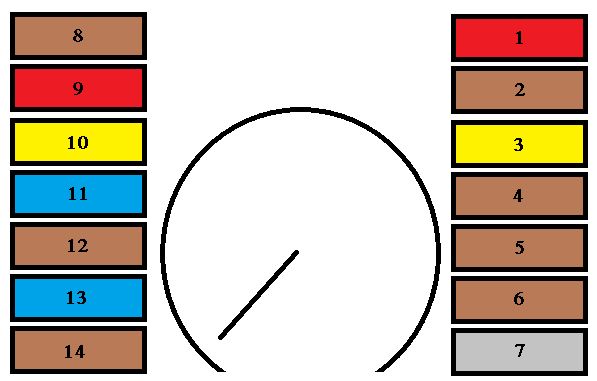
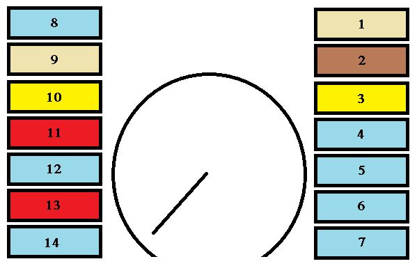
Fuse box in passenger compartment

| Fuse | Ampere rating [A] | Circuit protected |
| 1 | 10 | Reversing lights, tachometer*, dim lamps*; fuel gauge, water in fuel sensor (diesel); warning lights for: battery charge, water temperature, oil pressure, coolant level, brakes, choke; water in fuel (diesel) |
| 2 | 25 | Direction indicators, fuel gauges; seat heating*; additional heater/ventilation pum; gauges*; oil temperature; coolant temperature; oil pressure; heater/ventilation; air conditioning; warning lamps; battery charge, water in fuel, coolant temperature, oil pressure, coolant, level, brakes, choke, ABS |
| 3 | 25 | Map reading lamp, brake lights; windscreen wipe/wash, front and rear; tachometer*; headlamp wash*; car radio (+accessories); glovebox*; relay-window lift mechanism*; relay – rear screen demist; time-lag relay – interior lighting* |
| 4 | 15 | Spot lamps* |
| 5 | 10 | Hazard lamps |
| 6 | — | Not in used |
| 7 | 25 | Clock; interior lights; boot lighting*; centralised lock* car radio (+ permanent); power supply to towbar; supply relay – window lift mechanism |
| 8 | 30 | Horn; rear screen demist; cigar lighter |
| 9 | 25 | Front electric windows* |
| 10 | 5 | Rear fog lamp |
| 11 | 5 | Rear side lamps – left; license plate lamp |
| 12 | 5 | Rear side lamp – right |
| 13 | 5 | Fascia panel lighting; front side lamps |
| 14 | 15 | Petrol feed punp* |
| * According to model | ||
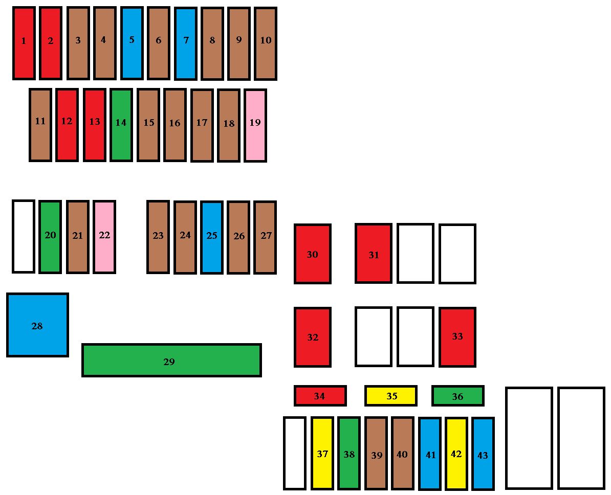
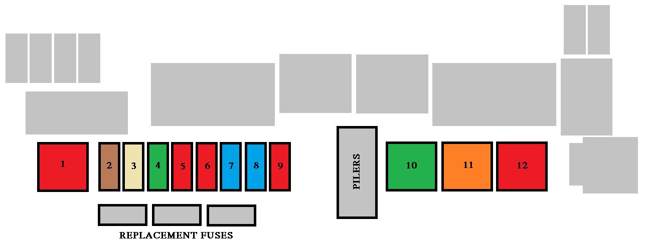
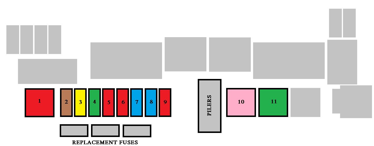
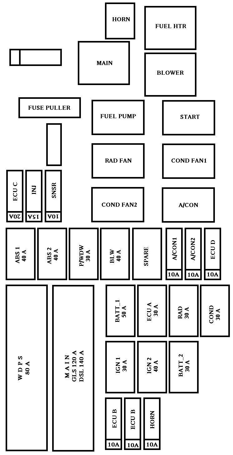
Fuse box in engine bay
| Circuit protected | Ampere rating [A] |
| ABS* | 30 |
| Anti-lock system supply* | 15 |
| Engine fan | 30 |
| Lambda probe* | 10 |
| * According to model | |
WARNING: Terminal and harness assignments for individual connectors will vary depending on vehicle equipment level, model, and market.