Ranault Capture (from 2013) – fuse box diagram
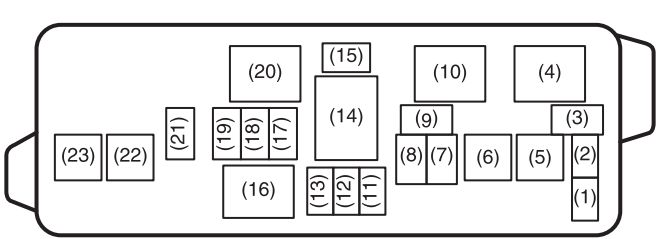
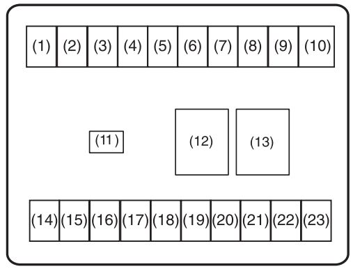
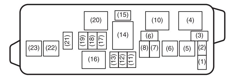
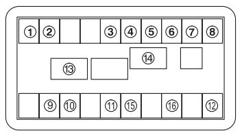
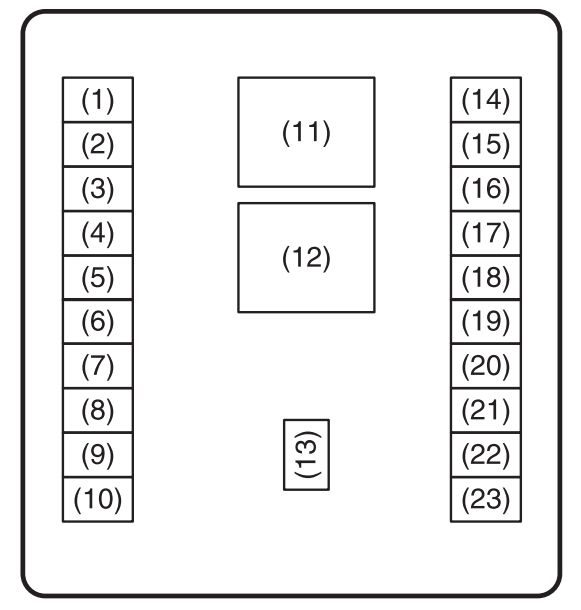
Fuse box
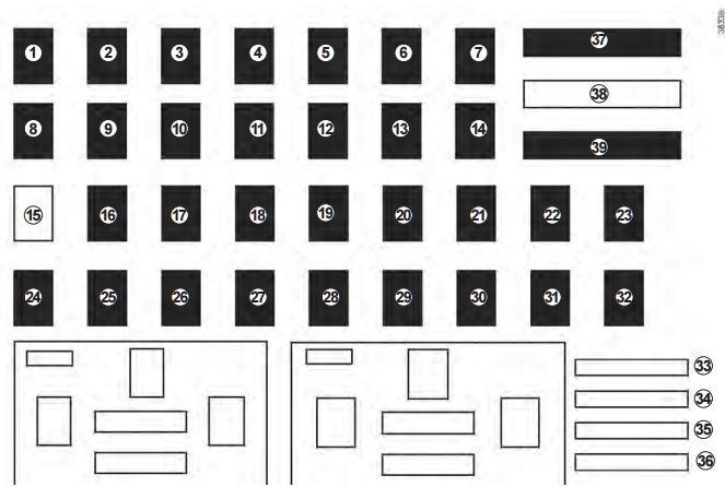
| Fuse | Allocation |
| 1 | Power-assisted steering |
| 2 | Injection |
| 3 | Airbag |
| 4 | Automatic gearbox, LPG |
| 5 | Dipped beam headlights |
| 6 | Front fog lights, front side lights, main beam headlights |
| 7 | Horn |
| 8 | Left-hand main beam headlight |
| 9 | Right-hand main beam headlight |
| 10 | Right-hand dipped beam headlight |
| 11 | Left-hand dipped beam headlight |
| 12 | Left-hand side lights |
| 13 | Right-hand side lights |
| 14 | Rear windscreen wiper |
| 15 | Empty location |
| 16 | Headlight beam adjustment |
| 17 | Daytime running lights |
| 18 | Brake lights |
| 19 | Electric door mirrors |
| 20 | ABS, ESP |
| 21 | Interior lighting |
| 22 | Vehicle On/Off button |
| 23 | Radio |
| 24 | Passenger compartment ECU |
| 25 | Passenger compartment ECU |
| 26 | Direction indicator lights |
| 27 | Central locking of opening elements |
| 28 | UCE energy management |
| 29 | UCE energy management |
| 30 | Alarm |
| 31 | Instrument panel |
| 32 | Cigarette lighter |
| 33 | Rear fog lights |
| 34 | Front seat heating |
| 35 | Rear screen de-icer |
| 36 | Towbar |
| 37 | Front windscreen wiper |
| 38 | Empty location |
| 39 | Front windscreen wiper |
WARNING: Terminal and harness assignments for individual connectors will vary depending on vehicle equipment level, model, and market.