Ford Fiesta (1995 – 1999) – fuse box diagram
Year of production: 1995, 1996, 1997, 1998, 1999
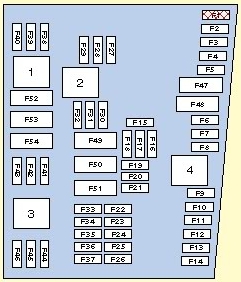
Central fusebox in passenger compartment
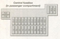
| Fuse | Ampere rating [A] | Circuit protected |
| F1 | 15 | Cigar lighter |
| F2 | 20 | Interior lights, clock, radio memory |
| F3 | — | Not used |
| F4 | 15 | Heated rear sensor/exterior mirrors |
| F5 | 20 | Horn, alarm |
| F6 | 10 | LH sidelights |
| F7 | 10 | RH sidelight |
| F8 | 15 | Central locking, electric mirrors |
| F9 | 15 | Seat hight adjustment |
| F10 | 15 | Heated front seats |
| F11 | 30 | Central locking, electric windows |
| F12 | 20 | Wiper motor, screen washer pump |
| F13 | 15 | Brake light, instrument panel |
| F14 | 10 | Air bag |
| F15 | 10 | Heated mirror |
| F16 | 30 | Heater blower motor |
| F17 | 15 | Direction indicators |
| F18 | 15 | Ignition |
| F19 | 10 | Engine management, alarm, radio |
| F20 | 30/10 | Head washer (Skandinavia only), Dim/dip (RHD only) |
| F21 | — | Not used |
| F22 | 10 | Diagnostic plug |
| F41 | 10 | Rear fog light (depending on country) |
| F42 | 10 | Rear fog light (depending on country) |
| F43 | 10 | Daytime running lights (Scandinavia only). High beam locking diode (RHD only) |
| F44 | 20 | Door locking module |
| F45 | 15 | Luggage compartment release (central locking only) |
Auxiliary fusebox in engine bay
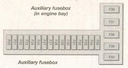
| Fuse | Ampere rating [A] | Circuit protected |
| F1 | — | Protection diode for EEC V relay |
| F2 | — | Not used |
| F3 | — | Not used |
| F23 | 10 | LH main beam |
| F24 | 10 | PH main beam |
| F25 | 10 | LH low beam |
| F26 | 10 | RH low beam |
| F27 | 10 | Lambda sensor (petrol) |
| 15 | Fuel heater (diesel) | |
| F28 | 15 | Engine management |
| F29 | 20 | Reversing lights/compressor cluch (a/c) |
| F30 | 3 | ABS module |
| F31 | 30 | ABS module |
| F32 | 3 | EEC Vignition module |
| F33 | 30 | ABS module |
| F34 | 25 | Transmission |
| F35 | 10 | Fuel pump (petrol) |
| 3 | PATS module (diesel engine) | |
| F36 | 60 | Engine management, blowe, fuel pump, glow plug (diesel) |
| F37 | 40 | Heated windscreen |
| F38 | 60 | Central locking, heated rear screen |
| F39 | 60 | Headlight washer |
| F40 | 60 | Ignition lock |
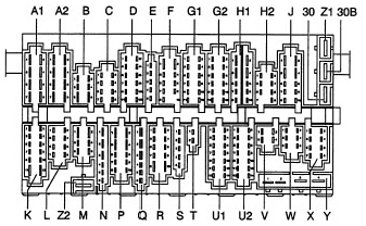
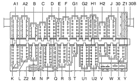
WARNING: Terminal and harness assignments for individual connectors will vary depending on vehicle equipment level, model, and market.


 - bezpieczniki")