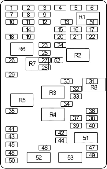
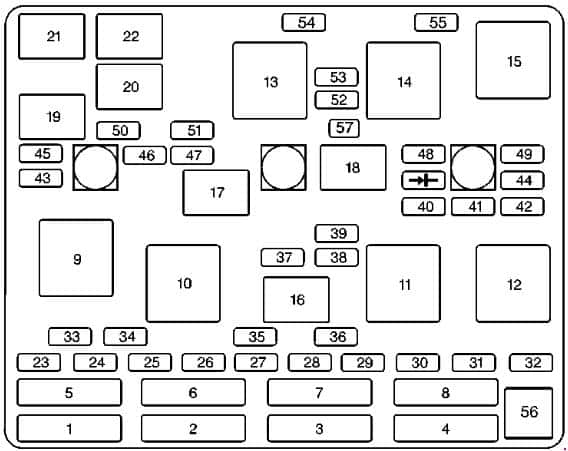
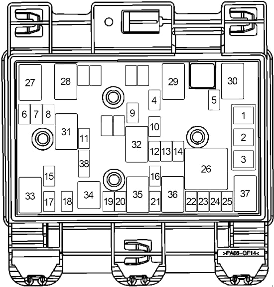
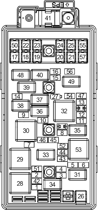
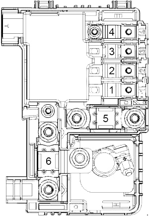
| No.
|
A
|
Protected Component |
| 1 |
10 |
Evaporative Emission (EVAP) Canister Vent Solenoid, Transmission Control Module (TCM) |
| 2 |
10 |
’05-’09 (5.3L, 6.0L): Body Control Module (BCM), Theft-Deterrent Alarm, Theft Deterrent Control Module |
| 3 |
15 |
Windshield Washer Fluid Pump |
| 4 |
10 |
High Beam Headlamps, High Beam Relay |
| 5 |
10 |
’05-’09 (5.3L, 6.0L): Heated Oxygen Sensor |
| 6 |
10 |
4.2L: Air Conditioner Relay |
| 10 |
’05-’09 (5.3L, 6.0L): Heated Oxygen Sensor |
| 7 |
– |
– |
| 8 |
25 |
’03: Transfer Case Shift Control Module, Transfer Case Encoder Motor |
| 30 |
’04-’09: Transfer Case Encoder Motor, Transfer Case Shift Control Module |
| 9 |
20 |
’05-’09 (5.3L, 6.0L): Fuel Injectors, Ignition Coils (Right Side) |
| 15 |
’03-’04 (5.3L): Fuel Injectors, Ignition Coils (Right Side) |
| 10 |
’06-’09 (4.2L): Heated Oxygen Sensor |
| 10 |
15 |
’03-’04 (5.3L): Fuel Injectors, Ignition Coils (Left Side) |
| 15 |
Evaporative Emission (EVAP) Canister Purge Solenoid, Mass Air Flow (MAF)/Intake Air Temperature (IAT) Sensor, Valve Lifter Oil Manifold (VLOM) Assembly |
| 11 |
15 |
5.3L, 6.0L: Throttle Actuator Control (TAC) Module – Powertrain Control Module (PCM) / Engine Control Module (ECM) |
| 12 |
10 |
’03-’04: Body Control Module (BCM), Theft-Deterrent Alarm, Theft Deterrent Control Module |
| 20 |
’05-’09 (5.3L, 6.0L): Fuel Injectors, Ignition Coils (Left Side) |
| 10 |
’05-’09 (4.2L): Body Control Module (BCM), Theft-Deterrent Alarm, Theft Deterrent Control Module |
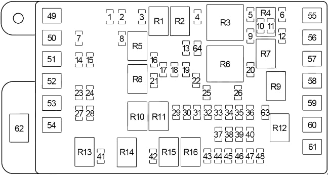
| 13 |
10 |
Trailer Connector (Right Turn Signal) |
| 14 |
30 |
Automatic Level Control Compressor |
| 15 |
10 |
Trailer Connector (Back-Up Lamps) |
| 16 |
10 |
Trailer Connector (Left Turn Signal) |
| 17 |
5 |
Saab: Ignition Switch |
| 18 |
25 |
Stoplamp Switch |
| 19 |
20 |
Cigar Lighter, Data Link Connector (DLC) |
| 20 |
10 |
5.3L, 6.0L: Air Conditioner Relay |
| 21 |
20 |
Fuel Pump Relay, Powertrain Control Module (PCM) |
| 22 |
15 |
Electronic Adjustable Pedals (EAP) Relay |
| 23 |
10 |
Right High-Beam Headlamp |
| 24 |
10 |
Left High-Beam Headlamp |
| 25 |
10 |
Powertrain Control Module (PCM) / Engine Control Module (ECM) |
| 26 |
10 |
Stop Lamp Switch, A/T Shift Lock Actuator |
| 27 |
10 |
Right Low-Beam Headlamp |
| 28 |
10 |
Left Low-Beam Headlamp |
| 29 |
15 |
Headlamp Driver Module (HDM) Relay |
| 30 |
25 |
Turn Signal/Hazard Flasher Module |
| 31 |
10 |
Body Control Module (BCM) |
| 32 |
10 |
Inflatable Restraint Front Passenger Pressure System (PPS) Module, Inflatable Restraint Sensing and Diagnostic Module (SDM), Rollover Sensor |
| 33 |
10 |
’03-’08: Engine Cooling Fan (Fan Driver Module) |
| 34 |
10 |
Ignition Relay No.1, Air Conditioner Relay, Park/Neutral Position (PNP) Switch, Headlamp Leveling Actuators, Inverting Driver Module, Stop Lamp Switch, Traction Control Switch, Headlamp Leveling Switch, Instrument Panel Cluster, Turn Signal/Multifunction Switch, Inside Rearview Mirror |
| 35 |
10 |
’03: EVAP Canister Purge Solenoid, EVAP Canister Vent Solenoid |
| 15 |
’04-’09: Electronic Adjustable Pedals (EAP) Relay, Back-Up Lamps (Park/Neutral Position (PNP) Switch) |
| 36 |
15 |
4.2L: Powertrain Control Module (PCM) / Engine Control Module (ECM), Fuel Injectors, Ignition Coils |
| 15 |
5.3L, 6.0L: Engine Control Module (ECM) |
| 37 |
15 |
’04-’08 (4.2L): Secondary Air Injection (AIR) Pump Relay, Secondary Air Injection (AIR) Pump, Secondary Air Injection (AIR) Solenoid |
| 38 |
10 |
4.2L: Powertrain Control Module (PCM), Throttle Actuator Control (TAC) Module |
| 15 |
’03-’04 (5.3L): Heated Oxygen Sensors |
| 15 |
’09: Secondary Air Injection (AIR) Pump Relay |
| 39 |
15 |
’03: Back-Up Lamps (Park/Neutral Position (PNP) Switch) |
| 10 |
’04-’05: EVAP Canister Purge Solenoid, EVAP Canister Vent Solenoid |
| 40 |
10 |
’03-’05 (4.2L): Heated Oxygen Sensors |
| 15 |
’03-’04 (5.3L): Heated Oxygen Sensors |
| 15 |
’05-’09 (5.3L, 6.0L): 1-2 Shift Solenoid (1-2 SS) Valve, 2-3 Shift Solenoid (2-3 SS) Valve, 3-2 Shift Solenoid (2-3 SS) Valve, Torque Converter Clutch (TCC) Solenoid Valve, Torque Converter Clutch Pulse Width Modulation (TCC PWM) Solenoid Valve, Transmission Control Module (TCM) |
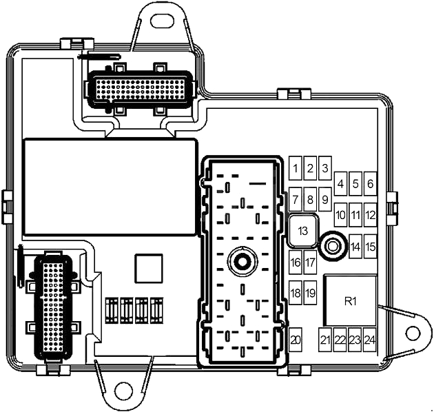
| 41 |
20 |
Headlamp Washer Relay, Rear Window Wiper Motor Relay |
| 42 |
15 |
Front Fog Lamp Relay |
| 43 |
30 |
Trailer Brake Wiring |
| 44 |
15 |
Horn Relay |
| 45 |
10 |
Instrument Panel Cluster (IPC) |
| 46 |
10 |
’05-’09 (5.3L, 6.0L): Engine Control Module (ECM) |
| 47 |
15 |
’05-’09: Regulated Voltage Control |
| 48 |
15 |
’09: Engine Control Module (ECM) |
| 49 |
30 |
Trailer Connector |
| 50 |
60 |
ABS – Electronic Brake Control Module (EBCM) |
| 51 |
60 |
4.2L: Secondary Air Injection (AIR) Pump Relay |
| 52 |
60 |
’06-’09: Vehicle Stability Enhancement System (VSES) – Electronic Brake Control Module (EBCM) |
| 53 |
– |
– |
| 54 |
– |
– |
| 55 |
40 |
’06-’09: Blower Motor Control Module, Blower Motor Resistor Assembly |
| 56 |
40 |
Starter Relay, Ignition Switch |
| 57 |
– |
– |
| 58 |
40 |
’03-’05: Blower Motor Resistor Assembly (HVAC Manual), Blower Motor Control Processor (HVAC Auto) |
| 59 |
40 |
Ignition Switch |
| 60 |
– |
– |
| 61 |
– |
– |
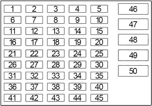
| 62 |
125 |
Fuse Block (Passenger Compartment) |
| 63 |
15 |
’09: Evaporative Emission (EVAP) Canister Purge Solenoid, Mass Air Flow (MAF)/Intake Air Temperature (IAT) Sensor, Valve Lifter Oil Manifold (VLOM) Assembly |
| 64 |
15 |
’09 (Saab): Evaporative Emission (EVAP) Canister Purge Solenoid, Mass Air Flow (MAF)/Intake Air Temperature (IAT) Sensor |
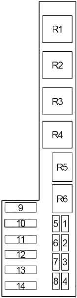
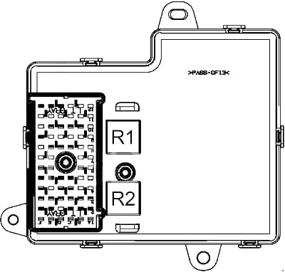
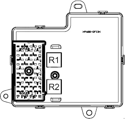
| Relay |
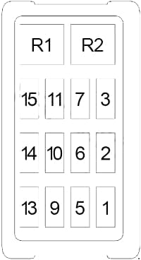
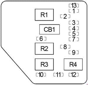
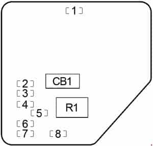
| R1 |
Windshield Washer Fluid Pump |
| R2 |
High Beam Headlamps |
| R3 |
’03-’04 (5.3L): Ignition (Fuse: “5”, “10”, “11”) |
| ’05-’09: Powertrain Control Module (PCM) / Engine Control Module (ECM) |
| R4 |
4.2L: Air Conditioner |
| ’09: Secondary Air Injection (AIR) Pump |
| R5 |
– |
| R6 |
Starter |
| R7 |
5.3L, 6.0L: Air Conditioner |
| R8 |
Fuel Pump |
| R9 |
Electronic Adjustable Pedals (EAP) |
| R10 |
Engine Cooling Fan |
| R11 |
Headlamp Driver Module (Low Beam Headlamps) |
| R12 |
– |
| R13 |
Headlamp Washer System |
| R14 |
Rear Window Washer Fluid Pump |
| R15 |
Front Fog Lamp |
| R16 |
Horn |