Courtesy lights, clock feed, key warning buzzer, headlight warning buzzer, seat back latch relay and illuminated entry
8
15
Standard: Parking, tail and license lights
10
Console: Parking, tail and license lights
9
—
—
10
20
Radio, power antenna and CB radio
11
20
Accessories, air conditioning clutch, heated rear window relay coil, deck lid release, speed control and illuminated entry
12
6
Circuit Breaker Windshield wipers and wiper/washers
13
15
Stop and hazard warning lights
14
15
Turn signal and back-up lights
15
30
Air conditioning and automatic temperature control blower
16
—
—
17
20
Power windows
Circuit Breaker:
Headlights – An 22 amp. C.B. is integral with headlight switch.
Fusible Links:
16 Gauge — In wiring at starter relay to protect electric rear window defroster.
16 Gauge — In wiring at starter relay to protect battery power circuit to headlight switch and fuse panel, except stop and hazard lights.
16 Gauge — In wiring at starter relay to protect battery power circuit to ignition switch and stop and hazard lights.
20 Gauge — In wiring at starter relay to protect engine compartment light.
20 Gauge — On California 8 cylinder models, a link is located in the engine wiring at the main feed connection to protect the battery power circuit to electric choke heater, and the battery power circuit to the MCU control module and engine sensors.
In-Line Fuse:
A 2 amp. in-line fuse is located on the visor to protect the lighted vanity mirror
A 15 amp. fuse located in the wiring assembly in the package tray luggage compartment
WARNING: Terminal and harness assignments for individual connectors will vary depending on vehicle equipment level, model, and market.
Automatic light warning indicators and carburetor circuits
3
—
—
4
20
Horn and cigar lighter
5
25
Cigar lighters and tailgate window key switch
30
Circuit Breaker: Door locks, tailgate window key switch, lighters and power seats
6
—
—
7
15
Courtesy lights, illuminated entry, clock and CB radio
8
15
License, tail, parking and coach lights
9
—
—
10
15
Radio, power antenna, CB radio and premium sound system
11
20
Air conditioning clutch, cornering lights, rear window de-icer, trunk release, speed control, police circuits, illuminated entry, power window safety relay (4-dr) and digital clock
12
8.25
Circuit Breaker: Windshield wipers/washers and intermittent wipers
13
15
Hazard and stop lights
14
15
Turn signal lights, back-up lights and trailer
15
30
Heater and air conditioning blower
16
—
—
17
25
Tailgate windows and instrument panel switch
30
Circuit Breaker: Power windows
Circuit Breaker:
Headlights – An 18 amp. C.B. is integral with headlight switch.
Power Windows — A 20 amp. C.B. is located on the fuse panel on 2-door models, or at the starter relay on 4-door models.
Fusible Links:
A fusible link located at the wiring harness of the starter relay protects the followng circuits, heated rear window, trailer towing brakes and lights, and the air bag feed.
In-Line Fuse:
A 2 amp. in-line fuse is located on the visor to protect the lighted vanity mirror
WARNING: Terminal and harness assignments for individual connectors will vary depending on vehicle equipment level, model, and market.
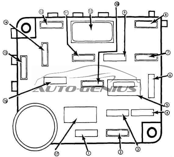
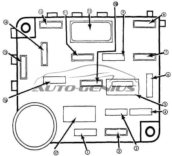
Mercury Grand Marquis (1979 – 1982) – fuse box diagram
Year of production: 1979, 1980, 1981, 1982
Fuse box diagram
Mercury Grand Marquis – fuse box diagram
№
A
Protected Component
1
5
Instrument illumination
2
10
Automatic light warning indicators and carburetor circuits
3
—
—
4
20
Horn and cigar lighter
5
25
Cigar lighters and tailgate window key switch
30
Circuit Breaker: Door locks, tailgate window key switch, lighters and power seats
6
—
—
7
15
Courtesy lights, illuminated entry, clock and CB radio
8
15
License, tail, parking and coach lights
9
—
—
10
15
Radio, power antenna, CB radio and premium sound system
11
20
Air conditioning clutch, cornering lights, rear window de-icer, trunk release, speed control, police circuits, illuminated entry, power window safety relay (4-dr) and digital clock
12
8.25
Circuit Breaker: Windshield wipers/washers and intermittent wipers
13
15
Hazard and stop lights
14
15
Turn signal lights, back-up lights and trailer
15
30
Heater and air conditioning blower
16
—
—
17
25
Tailgate windows and instrument panel switch
30
Circuit Breaker: Power windows
Circuit Breaker:
Headlights – An 18 amp. C.B. is integral with headlight switch.
Power Windows — A 20 amp. C.B. is located on the fuse panel on 2-door models, or at the starter relay on 4-door models.
Fusible Links:
A fusible link located at the wiring harness of the starter relay protects the followng circuits, heated rear window, trailer towing brakes and lights, and the air bag feed.
In-Line Fuse:
A 2 amp. in-line fuse is located on the visor to protect the lighted vanity mirror
WARNING: Terminal and harness assignments for individual connectors will vary depending on vehicle equipment level, model, and market.