Mercury Tracer (1991 – 1996) – fuse box diagram
Year of production: 1991, 1992, 1993, 1994, 1995, 1996
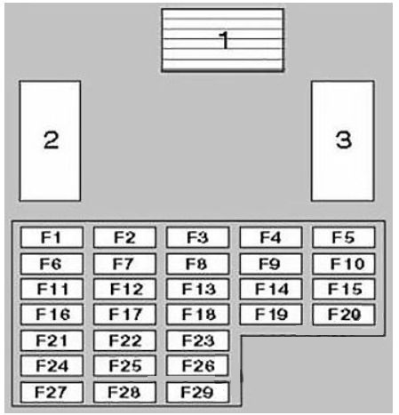
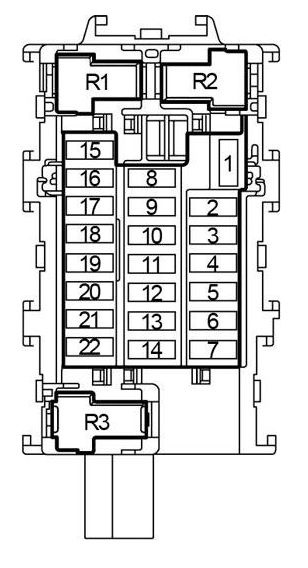
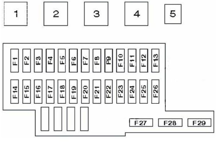
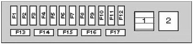
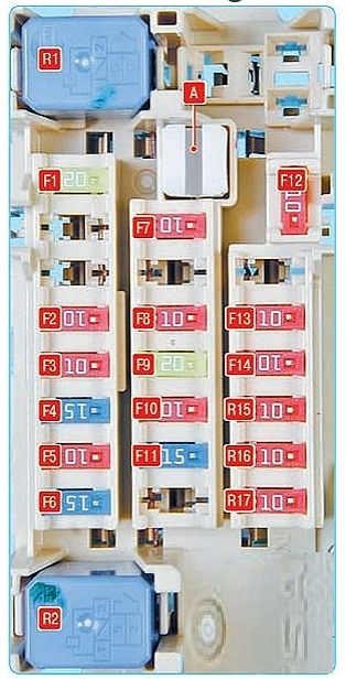
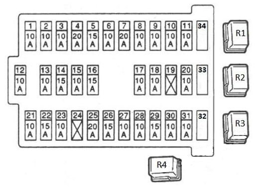
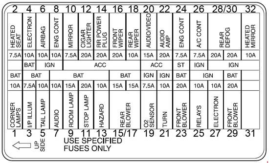
Passenger Compartment Fuse Box
| № | A | Description components |
| 1 | 10 | A/C On Indicator, Air Conditioner Relay, Air Conditioner Switch, Daytime Running Lamp Module, Daytime Running Lamp Relay, Rear Wiper and Washer Motor, Wide-Open Throttle Cutout Relay |
| 2 | 30 | Door Lock Motor |
| 3 | 20 | Brakelamp, Electronic Automatic Transaxle Module, Powertrain Control Module, High-Mount Brakelamp, Horn, Shift Interlock System, Speed Control |
| 4 | 15 | Hazard Flashers, Front and Rear Turn Lamp, Turn Indicator Lamp |
| 5 | 30 | Passive Belt Control Module, Passive Belt Motor |
| 6 | 15 | Powertrain Control Module (1.8L engine), Exterior Lamps, Interior Illumination, Parking Lamp Relay, Warning Chime Module |
| 7 | 15 | Dome and Map Lamp, Door Lock Switch, Engine Room, Ignition Key Illumination, Luggage Lamp, Premium Soundlifier, Radio (memory), Powertrain Control Module, Shift Interlock System, Visor Mirror Lamp, Warning Chime Module |
| 8 | 30 | Power Window Motor |
| 9 | 15 | Moon Roof Motor |
| 10 | 15 | Cooling Fan System, Powertrain Control Module Power Relay |
| 11 | 15 | Air Bag Diagnostic Module, Backup Lamps, Cluster, Flasher Unit, Passive Belt Control Module, Powertrain Control Module (Canada Only), Shift-Lock System, Speed Control, Turn Signal Flashers, Warning Chime |
| 12 | 15 | Instrument Panel Dimmer Module, Radio, Remote Control Mirror |
| 13 | 20 | Front Wiper and Washer Motor, Interval Governor, Interval Wiper and Washer Switch |
| 14 | 20 | Powertrain Control Module (1.8L engine), Rear Window Defrost |
| 15 | 30 | Circuit breaker: Blower Motor, Powertrain Control Module (1.8L engine) |
| 16 | 20 | 1.8 L (BP): Horn (on joint box side, not shown) |
| 10 | 1.9 L (CVH): Heated Exhaust Gas Oxygen Sensor (on joint box side, not shown) Horn (on joint box side, not shown) | |
| 17 | 20 | Cigar Lighter (on joint box side) |
| 18 | 10 | 1.8 L (BP): Anti-lock Brake System |
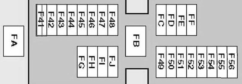
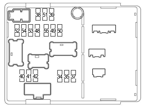
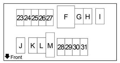
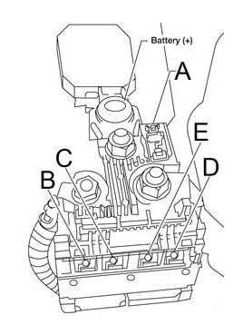
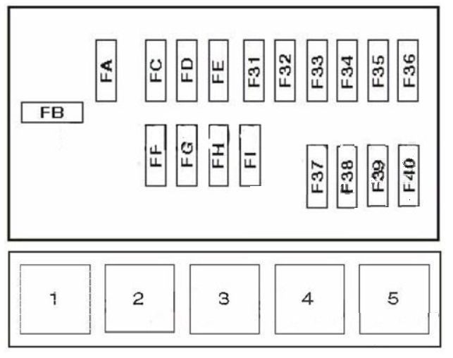
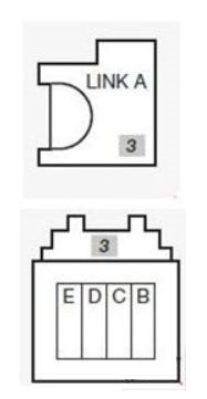
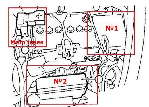
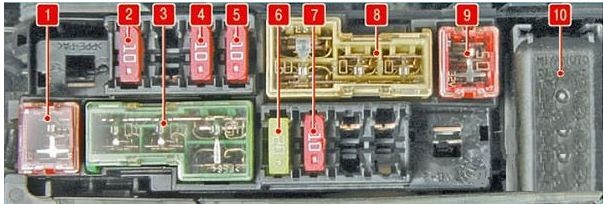
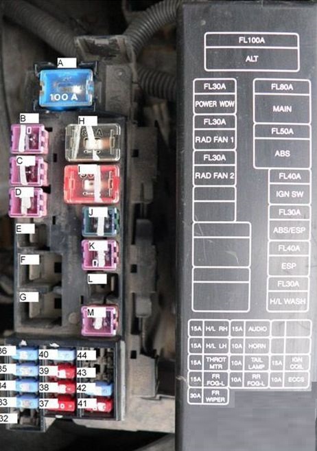
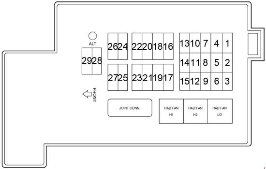
Fuse box in engine compartment
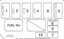
| № | A | Description components |
| 1 | 30 | Charging System (1.8L Engine), Fuel Injection System |
| 2 | 30 | Daytime Running Lamps (Canada), Fog Lamps, Headlamps, High Beam Indicator |
| 3 | 80 | 1.8 L (BP): Charging System, Engine Compartment Fuse Panel (ABS, A/C, BTN, Fan, Horn), Engine Controls, Instrument Cluster (Manual Transaxle Only), Instrument Panel Fuse Panel (Cigar, Defrost, Engine ABS, Heater, Meter, Power Window, Radio, Rear Wiper, Sun Roof), Starting System |
| 100 | 1.9 L (CVH): Charging System, Engine Compartment Fuse Panel (ABS, A/C, BTN, Fan), Engine Controls, Instrument Cluster (Manual Transaxle Only), Instrument Panel Fuse Panel (Cigar, Defrost, Engine ABS, Heater, HEGO, Meter, Power Window, Radio, Rear Wiper, Sun Roof), Starting System | |
| 4 | 60 | 1.8 L (BP): Instrument Panel Fuse Panel (Belt, Door Lock, Hazard, Room, Stop, Tail) |
| 40 | 1.9 L (CVH): Charging System (1.9L Engine), Instrument Panel Fuse Panel (Belt, Door Lock, Hazard, Room, Stop, Tail) | |
| 5 | 30 | 1.8 L (BP) – MTX: Cooling Fan System |
| 40 | 1.9 L (CVH) and 1.8 L (BP) – ATX: Cooling Fan System | |
| 6 | 20 | 1.8 L (BP): Air Conditioner Magnet Clutch |
| 10 | 1.9 L (CVH): Air Conditioner Magnet Clutch, Powertrain Control Module | |
| 7 | 10 | 1.8 L (BP): Fuel Pump Relay, Powertrain Control Module |
| 20 | 1.9 L (CVH): Fuel Pump | |
| 8 | 60 | 1.8 L (BP): Anti-lock Brake System |
| 9 | 10 | Air Bag Diagnostic Module |
| 10 | 20 | 1.8 L (BP): Fuel pump |
| 10 | 1.9 L (CVH): OBD-II (Data link connector) |
WARNING: Terminal and harness assignments for individual connectors will vary depending on vehicle equipment level, model, and market.