Hyundai Centennial (2010) – fuse box diagram
Year of production: 2010
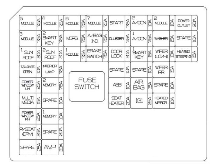
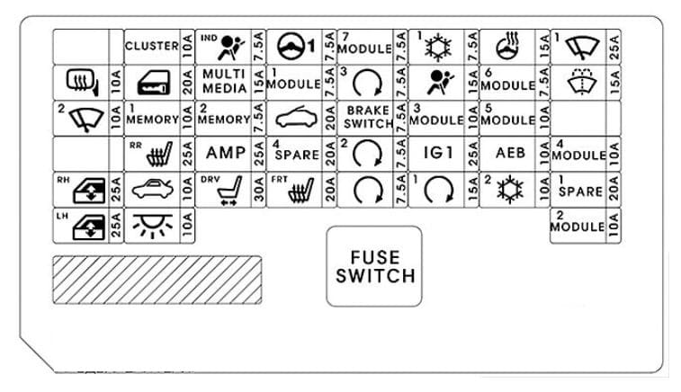
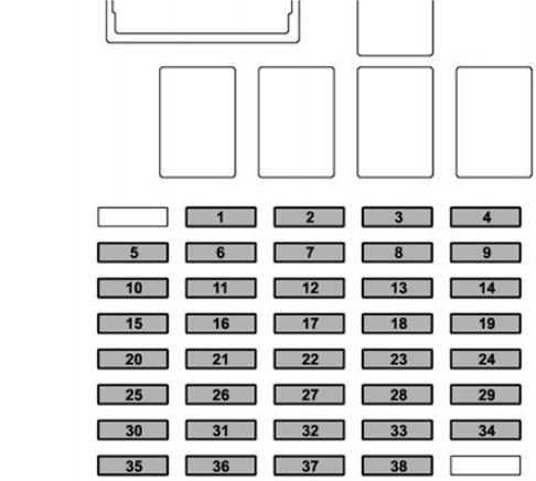
Instrument panel (Driver’s side fuse panel)
| Description | Ampere rating [A] | Protected component |
| P/WDW(RH) | 30 | Rear Power Window Module RH, Passenger Power Window Module |
| P/WDW(LH) | 30 | Rear Power Window Module LH, Driver Power Window Module |
| CHASSIS UNIT | 10 | Steering Angle Sensor, Console Switch LH/RH, ECS Control Module, Pre-Safe Seat Belt LH/RH, Tire Pressure Monitoring Module |
| CRUISE SW | 10 | Multifunction Switch (Remocon), Crash Pad Switch, A/C Control Module, Alternator, Instrument Cluster, Rear Seat Warmer Module LH/RH, Rear CCS Control Module LH/RH, Driver/Passenger CCS Control Module (With CCS), Driver/Passenger Seat Warmer Module (W/O CCS), Center Facia Switch |
| ESCL SW | 10 | FOB Holder, Start Stop Button Switch |
| CLUSTER | 10 | Instrument Cluster |
| A/CON(IG1) | 10 | A/C Control Module, FOB Holder |
| KEY ILLUMINATION | 10 | Start Stop Button Switch, FOB Holder |
| P/DOOR(RL) | 15 | Rear Power Door Latch LH, Rear Door Window Curtain LH |
| IG KEY SUPPLY(IG1) | 30 | E/R Junction Box (Fuse : EHPS 10A, ECU(IG1) 10A, TCU 15A, ESP 10A, STOP LP 10A, AFLS 10A, INHIBITOR SW 10A, CRUISE 10A) |
| DR LOCK(LH) | 10 | Driver Door Module |
| P/DOOR(FL) | 15 | Front Door Mood Lamp LH, Driver Power Seat Switch, Driver Power Door Latch |
| A/BAG IND | 10 | Instrument Cluster (A/Bag IND.) |
| AFLS | 10 | Auto Head Lamp Leveling Device Sensor (W/O AFLS), Adaptive Front Lighting Module (With AFLS), Head Lamp LH/RH |
| ESCL-1 | 10 | PDM |
| RR DOOR MDL | 10 | Data Link Connector, Rear Smart Outside Handle LH/RH, Rear Door Module LH/RH |
| RR CURTAIN MTR | 10 | Rear Curtain Module |
| BODY UNIT-2 | 10 | Multifunction Switch, Tilt & Telescopic Module, Driver/Passenger Door Module, Power Trunk Lid Control Module, Electro Chromic Mirror, LDWS Camera, Front & Rear Parking Assist Control Module, EPB Control Module, Driver/Passenger IMS Control Module, E/R Junction Box (FAM) |
| BODY UNIT-1 | 10 | Multifunction Switch, Instrument Cluster (IND.), Power Trunk Lid Control Module, Driver/Passenger Door Module, Rear Curtain Module, E/R Junction Box (FAM), Front Smart Outside Handle LH/RH, Passenger IMS Control Module |
| P/HANDLE | 15 | Tilt & Telescopic Module |
| ECS | 15 | ECS Control Module |
| A/BAG | 15 | SRS Control Module |
| AUDIO(B+) | 15 | Audio, Front/Rear Monitor, AV Head Module, Rear Audio Switch, Media Module, Tunner Unit, MTS Unit |
| S/HTD ECU(FL) | 15 | Driver CCS Control Module (With CCS), Driver Seat Warmer Module (With CCS) |
| P/TRUNK | 30 | Power Trunk Lid Control Module |
| F/LID OPEN | 10 | Fuel Filler Switch |
| AUDIO(IG1) | 10 | AV Head Module, Audio, Active Headrest Sensor Module, Camera Module, MTS Unit |
| A/CON(B+) | 10 | Auto Light Sensor & Security Indicator, RF Receiver, A/C Control Module, Analog Clock |
| P/CONN | 30 | Fuse : A/CON (B+) 10A, AUDIO (B+) 15A, BODY UNIT-1 10A |
| S/HTD ECU(RL) | 15 | Rear CCS Control Module LH (With CCS), Rear Seat Warmer Module LH (W/O CCS) |
| DR LOCK(RH) | 15 | Passenger Door Module |
| ESCL-2 | 10 | IPM,PDM |
| A/CON(IG1) | 10 | A/C Control Module |
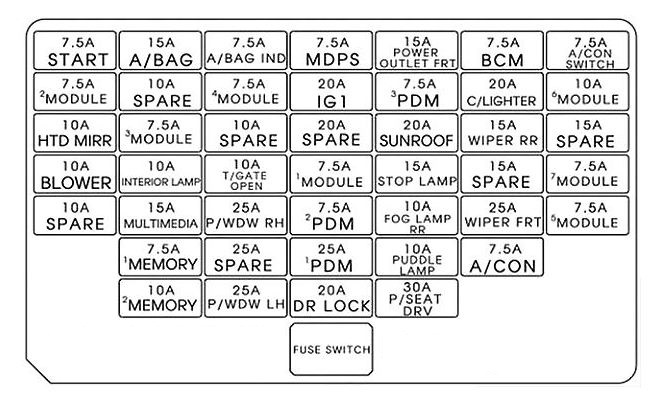
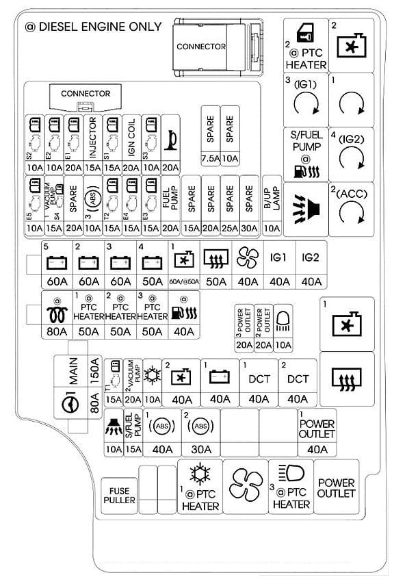
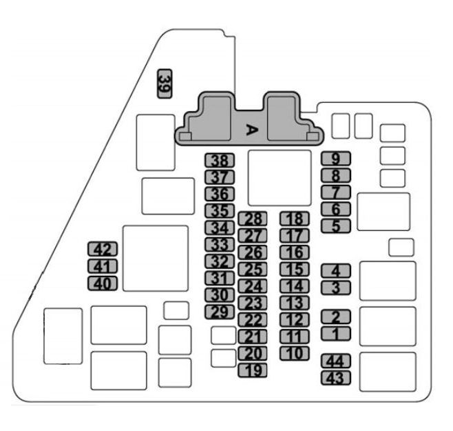
Instrument panel (Passanger’s side fuse panel)
| Description | Ampere rating [A] | Protected component |
| P/DOOR(FR) | 15 | Passenger Power Door Latch |
| ESCL | 25 | PDM |
| ICE BOX | 15 | Rear Console Switch, Cool Box |
| HTD STRG | 15 | Steering Wheel Heated |
| S/HTD ECU(FR) | 15 | Passenger CCS Control Module (With CCS), Passenger Seat Warmer Module (W/O CCS) |
| AUDIO(ACC) | 10 | Camera Module, Rear Audio Switch, Audio, Front Monitor, Media Module, AV Head Module, MTS Unit, RR MTS MIC |
| H/REST(FR) | 10 | Passenger Power Seat Switch |
| P/DOOR(RR) | 15 | Rear Power Door Latch RH, Rear Door Window Curtain RH |
| P/OUTLET(FR) | 10 | E/R Fuse & Relay Box(Front Power Outlet Relay) |
| ECM | 10 | Overhead Console Assembly (Sunroof Motor), Rain Sensor, Rear Curtain Module |
| P/SEAT(FR) | 20 | Passenger IMS Control Module (With IMS), Passenger Power Seat Relay Box (W/O IMS) |
| S/ROOF | 20 | Overhead Console Assembly (Sunroof Motor) |
| A/CON(ACC) | 10 | A/C Control Module, IPM, PDM, Center Facia Switch |
| P/OUTLET(RR) | 15 | Rear Accessory Socket |
| P/SEAT(RR) | 20 | Rear Power Seat Relay Box LH |
| BODY UNIT | 10 | Instrument Cluster (MICOM), Rheostat, Driver/Passenger CCS Control Module, Passenger Receiver, Rear CCS Control Module LH/RH, PDM, IPM |
| A/CON(IG2) | 10 | Active Incar Sensor, Ionizer, A/C Control Module, Rear Console Switch, Console Vent Temperature Actuator & Switch |
| IG KEY SUPPLY(IG2) | 30 | E/R Junction Box (Fuse : AQS 10A, WASHER 15A) |
| S/HTD ECU(RR) | 15 | Rear CCS Control Module RH (With CCS), Rear Seat Warmer Module RH (W/O CCS) |
| TPMS | 10 | Tire Pressure Monitoring Module, Electro Chromic Mirror |
| CONSOLE SW | 10 | Console Switch LH/RH, Massage Module, Vibrator Module |
| MIRROR | 10 | Outside Mirror LH/RH |
| LEG SUPPORT(RR) | 15 | Rear Power Seat Relay Box RH |
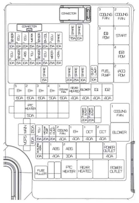
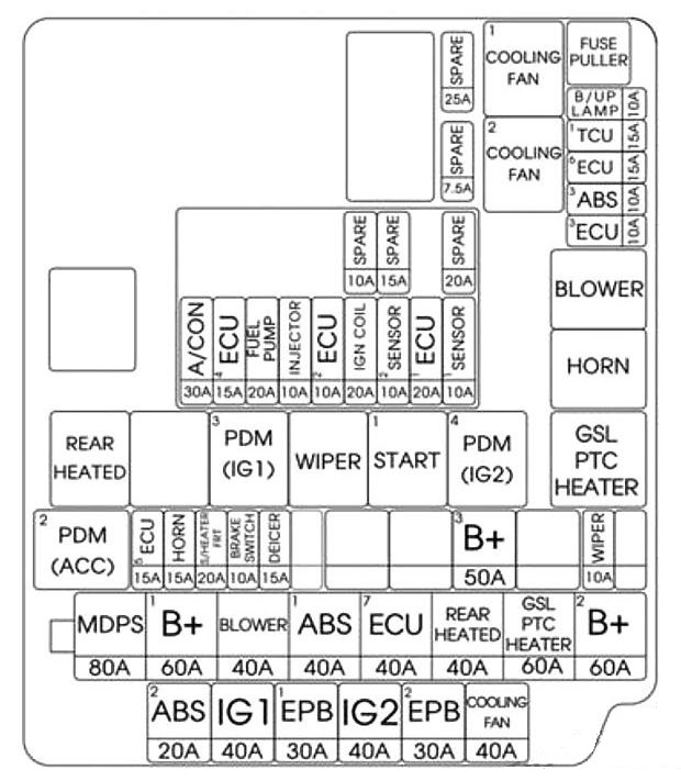
Engine compartment fuse panel
| Description | Ampere rating [A] | Protected component |
| ALT | 200 | Alternator |
| I/P POWER(LH) | 60 | I/P Junction Box LH |
| I/P POWER(RH) | 60 | I/P Junction Box RH |
| COOLING FAN | 60 | Cooling Fan Relay |
| EHPS | 80 | EHPS Motor |
| ECS | 40 | ECS Compressor Relay |
| AMP-1 | 40 | AV JBL AMP |
| AMP-2 | 30 | AMP |
| ESCL(ACC) | 30 | ESCL (ACC) Relay |
| ESP-1 | 30 | ESP Control Module, Multipurpose Check Connector |
| ESP-2 | 30 | ESP Control Module |
| ESCL(IGN1) | 30 | ESCL (IGN1) Relay |
| ESCL(IGN2) | 30 | ESCL (IGN2) Relay |
| P/SEAT(FR-LH) | 30 | Driver Lumbar Support Valve, Driver IMS Control Module, Driver Lumbar Support Switch |
| H/LP WASHER | 20 | Head Lamp Washer Relay |
| P/OUTLET(FR) | 25 | Front Power Outlet Relay, Cigar Lighter |
| TRUNK OPEN | 10 | Trunk Lid Open Relay |
| IMS | 10 | IMS Relay |
| STOP LP | 10 | Stop Lamp Relay, Stop Lamp Switch, IPM, ESP Control Module, High Mounting Stop Lamp |
| B/UP LP-1 (G8BA) | 10 | Back Up Lamp Relay |
| B/UP LP-2 (G8BA) | 10 | Rear Combination Lamp LH/RH, Electro Chromic Mirror, Rear Curtain Module, Audio, AV Head Module |
| WIPER | 30 | Electronic Control Wiper Module |
| FAM POWER-2 | 40 | FAM |
| FAM POWER-1 | 40 | FAM |
| START | 30 | Start Relay |
| WASHER | 15 | Washer Relay |
| AQS | 10 | AQS Sensor, Blower Relay, Electronic Control Wiper Module |
| HTD GLASS(FR) | 15 | HTD Glass(FR) Relay |
| IPM | 10 | IPM, H/LP(Low) Relay |
| HORN | 15 | Horn Relay |
| EPB-1 | 15 | EPB Control Module |
| EPB-2 | 15 | EPB Control Module |
| A/CON | 10 | A/C Control Module |
| BLOWER MOTOR | 40 | Blower Relay |
| PRESAFETY(LH) | 40 | Pre-Safe Seat Belt LH |
| HTD GLASS(RR) | 40 | HTD Glass(RR) Relay |
| PRESAFETY(RH) | 40 | Pre-Safe Seat Belt RH |
| ECU(IG1) | 10 | ECM |
| ESP | 10 | ESP Control Module, E/R Fuse & Relay Box (Multipurpose Check Connector) |
| EHPS | 10 | EHPS Module |
| AFLS | 10 | Head Lamp LH/RH |
| TCU | 15 | TCM |
| MIRROR HTD | 10 | A/C Control Module, Power Outside Mirror LH/RH |
| FUEL PUMP | 20 | Fuel Pump Relay |
| ROOM LP | 10 | Room LP Relay |
| ECU(B+) | 10 | ECM, TCM |
| STOP LP | 10 | Stop Lamp Switch, Alternator (G6DA), E/R Fuse & Relay Box (Stop Lamp Relay) |
| CRUISE | 10 | Smart Cruise Control Module |
| INHIBITOR SW | 15 | Alternator (G8BA), Transmission Range Switch (G6DA) |
| H/LP(LO-LH) | 15 | Head Lamp LH |
| H/LP(LO-RH) | 15 | Head Lamp RH |
| ENG SNSR-3 | 15 | ECM (G6DA), Injector #1~ 6 (G6DA), Fuel Pump Relay, Injector #1~ 8 (G8BA) |
| ENG SNSR-2 | 10 | Canister Purge Control Solenoid Valve, Oil Control Valve #1~4, Variable Intake Manifold Valve, E/R Fuse & Relay Box (Cooling Fan Relay), ECM, Mass Air Flow Sensor (G8BA) |
| ENG SNSR-1 | 10 | Mass Air Flow Sensor (G6DA), Oxygen Sensor #1 ~ 4, ECM, Camshaft Position Sensor (G8BA) |
| IGN COIL-2 | 15 | Condenser #1, Condenser #2(G6DA), Ignition Coil #1/3/5, Ignition Coil #7(G8BA) |
| IGN COIL-1 | 15 | Ignition Coil #2/4/6, Ignition Coil #8 (G8BA), Condenser #2 (G8BA) |
| ECU | 30 | Engine Control Relay |
WARNING: Terminal and harness assignments for individual connectors will vary depending on vehicle equipment level, model, and market.