Mercury Mountaineer (2002 -2005) – fuse box diagram
Year of production: 2002, 2003, 2004, 2005
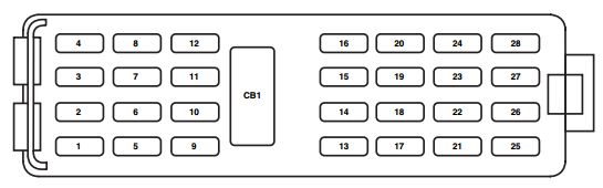
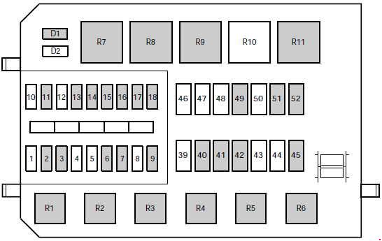
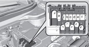
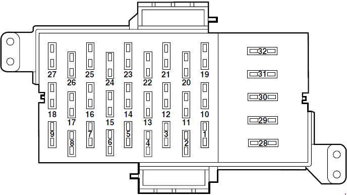
Passenger compartment fuse panel
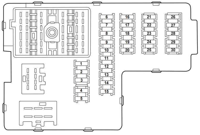
The fuse panel is located below the instrument panel on the driver’s side.
| No. | A | Circuits Protected |
| 1 | 30 | Memory seat module, Driver power seat (’03-’05), Driver power lumbar (’05) |
| 2 | 20 | Heated seats (’02), Moonroof |
| 3 | 20 | Radio, Amplifier, Power antenna (’02), DVD |
| 4 | 5 | Front wiper module |
| 5 | 15 | Flasher relay (Turn, hazards) |
| 6 | 10 | Right horn (’02), Key-in-chime (’03-’05) |
| 7 | 15 | Heated mirrors |
| 8 | 5 | ’04-’05: Heated PCV (4.0L engine only) |
| 9 | — | Not used (spare) |
| 10 | 10 | Heated backlight relay coil, Heated seat module (’02), Temp blend actuator (’02), A/C clutch contact |
| 11 | 20 | ’03-’05: Heated seats |
| 12 | 5 | ’02: Foglamp switch, 4×4 module |
| 13 | 5 | Overdrive cancel switch, Flex fuel sender (’02-’03) |
| 14 | 5 | PATS module |
| 15 | 5 | Rear wiper module, Cluster, TPMS (’02-’03) |
| 16 | 5 | Power mirror, Manual climate control, TPMS |
| 17 | 15 | Delayed acc. coil, Battery saver, Interior lamps (front and rear), Glove compartment lamp |
| 18 | 10 | Left horn (’02-’03), Flexible fuel pump (’04-’05) |
| 19 | 10 | RCM, PAD indicator (’02) |
| 20 | 5 | Memory driver seat switch, Driver seat module, Body Security Module (BSM), PATS LED, Sunload sensor (’02-’03) |
| 21 | 5 | Instrument cluster, Compass, Flasher coil |
| 22 | 10 | ABS, IVD Controller |
| 23 | 15 | ’02-’03: Brake pedal position switch, Driver brake applied relay, Redundant cruise deactivate switch |
| 24 | 15 | Cigar lighter, OBD II |
| 25 | 5 | Mode-Temperature actuator for auxiliary climate control, Trailer tow battery charge coil, TPMS (’04-’05) |
| 26 | 7.5 | Reverse park aid, Brake shift interlock, Approach lamp relay coil (’02), IVD switch |
| 27 | 7.5 | Automatic dimming mirror, Digital transmission range sensor, Backup lamps |
| 28 | 5 | Radio (Start)/DVD (Start) |
| 29 | 10 | Digital transmission range sensor, PWR feed to fuse #28 (Start feed) |
| 30 | 5 | Daytime Running Lamps (DRL), Remote solenoid, DEATC climate controller, Manual climate control, Manual climate control temp blend actuator |
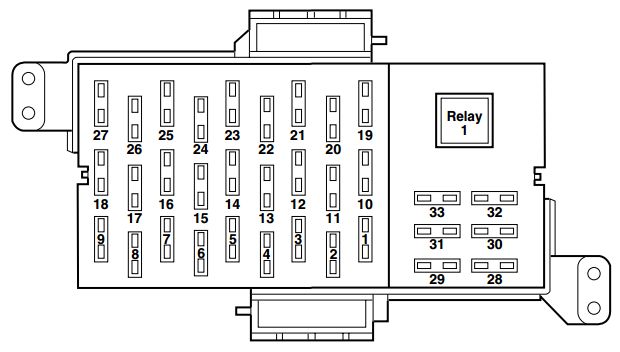
Passenger compartment fuse panel (top side)
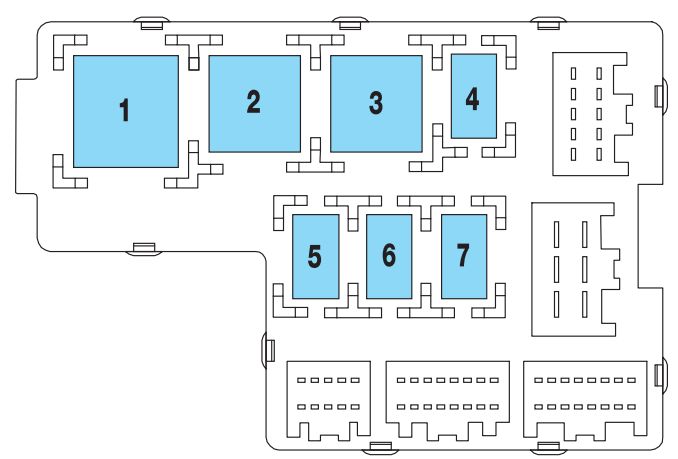
These relays are located on the reverse side of the passenger compartment fuse panel. To access the relays you must remove the passenger compartment fuse panel.
| No. | Circuits Protected |
| 1 | Flasher |
| 2 | Rear defrost |
| 3 | Delayed accessory |
| 4 | Open |
| 5 | Battery saver |
| 6 | Open |
| 7 | Open |
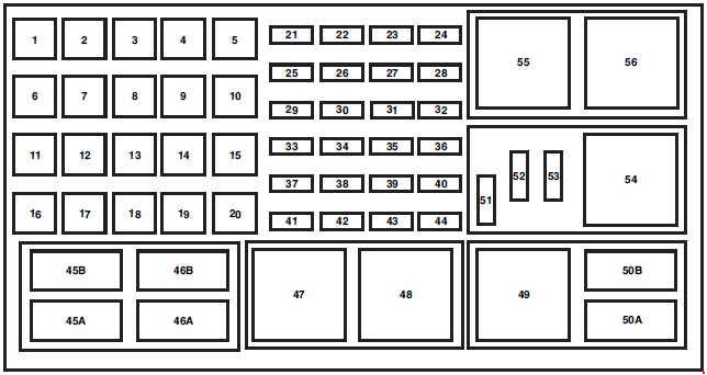
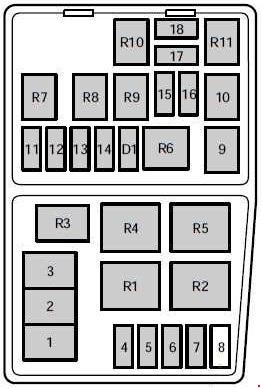
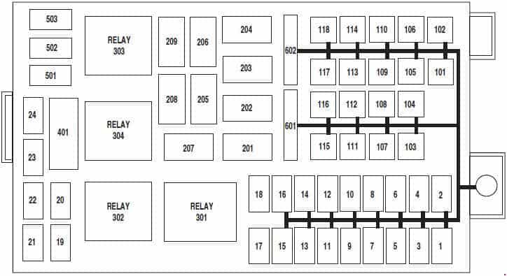
Engine Compartment Fuse Box
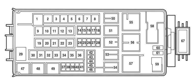
The power distribution box is located in the engine compartment. The power distribution box contains high-current fuses that protect your vehicle’s main electrical systems from overload.
| No. | A | Circuits Protected |
| 1 | 60 | PJB |
| 2 | 30 | BSM |
| 3 | — | Not used |
| 4 | 30 | Rear defrost |
| 5 | 40 | Anti-lock Brake System (ABS) pump |
| 6 | 60 | Delayed accessory, Power windows (’04-’05), Audio (’04-’05) |
| 7 | 20 | Power point #2 |
| 8 | — | Not used |
| 9 | 20 | Power point #1 |
| 10 | 30 | ABS module (valves) |
| 11 | 40 | PTEC (’02-’03), Powertrain Control Module (PCM) (’04-’05) |
| 12 | 50 | Ignition relay/Starter relay |
| 13 | 40 | Trailer tow battery. Trailer tow turn signals |
| 14 | 10 | ’02-’03: Daytime Running Lamps (DRL) (Canada) |
| 15 | 15 | Memory (KAPWR) (’02), Memory (PCM/DEATC/Cluster) (’03-’05), Courtesy lamps (’03-’05) |
| 16 | 15 | Headlamp switch (’02-’03), Foglamp switch (’03), Park lamps (’04-’05), Autolamp parklamps (’04-’05), Front foglamps relay coil (’04-’05) |
| 17 | — | Not used |
| 18 | 20 | 4×4 (v-batt 1) (’02-’03), PCM with two-speed 4×4 clutch (’04-’05) |
| 19 | 20 | High beam relay |
| 20 | 30 | Trailer electric brake module |
| 21 | 30 | Front wiper motor |
| 22 | 20 | Autolamp; Low beam |
| 23 | 30 | Ignition switch, PCM diode (’04-’05) |
| 24 | — | Not used |
| 25 | 15 | ’04-’05: Brake on-off |
| 26 | 15 | ’02-’03: Fuel pump |
| 20 | ’04-’05: Fuel pump | |
| 27 | 20 | Trailer tow lamps, Trailer tow back-up |
| 28 | 20 | Horn relay |
| 29 | 60 | PJB |
| 30 | 20 | Rear wiper motor |
| 31 | — | Not used |
| 32 | — | Not used |
| 33 | 30 | Auxiliary blower motor |
| 34 | 30 | Power seats, Adjustable pedals |
| 35 | 20 | Rear power point (’02) |
| 36 | 40 | Blower motor |
| 37 | 15 | A/C clutch relay/Transmission |
| 38 | 15 | Coil on plug (’02-’03), HEGO (’04-’05), VMV (’04-’05), CMS (’04-’05), ESM (’04-’05), CVS (’04-’05) |
| 39 | 15 | Injectors/Fuel pump relay |
| 40 | 15 | PTEC power (’02-’03), PCM power (’04-’05) |
| 41 | 15 | HEGO (’02-’03), VMV (’02-’03), CMS (’02-’03), PTEC (’02-’03), Coil on plug (’04-’05; 4.6L engine only), Ignition coil (’04-’05; 4.0L engine only) |
| 42 | 10 | Right low beam |
| 43 | 10 | Left low beam |
| 44 | 15 | Front foglamps |
| 45 | 5 | Brake pressure switch (’02) |
| 2 | Brake pressure switch (ABS) (’03-’05) | |
| 46 | 20 | High beams |
| 62 | 30 | Circuit Breaker: Delayed accessory (’02), Power windows (’03-’05) |
| Relay | ||
| 47 | Horn | |
| 48 | Fuel pump | |
| 49 | High beam | |
| 50 | Fog lamp | |
| 51 | ’02-’03: Daytime Running Lamps | |
| 52 | A/C clutch | |
| 53 | Trailer tow right turn | |
| 54 | Trailer tow left turn | |
| 55 | Blower motor | |
| 56 | Starter | |
| 57 | ’02-’03: PTEC ’04-’05: PCM |
|
| 58 | Ignition | |
| 59 | ’02-’03: Driver brake applied or Daytime Running Lamps | |
| Diode | ||
| 60 | PCM | |
| 61 | A/C clutch | |
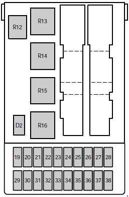
Rear Relay Box
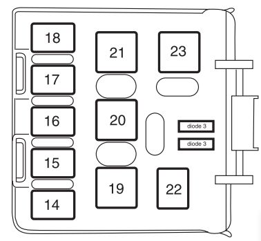
The relay box is located on the rear passenger side quarter trim panel. To access this box you must remove the trim panel.
| No. | Circuits Protected |
| 14 | Not used |
| 15 | Trailer tow back-up lamps |
| 16 | Not used |
| 17 | Not used |
| 18 | Not used |
| 19 | Trailer tow park lamps |
| 20 | Trailer tow battery charge |
| 21 | Not used |
| 22 | ’02: Approach lamps |
| 23 | Not used |
| Diode | |
| 3 | Not used |
| 4 | Not used |
Auxiliary relay box (trailer tow)
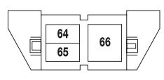
The relay box is located on the front right fender well underneath the speed control module.
| Relay | Description |
| Relay 64 | Trailer Tow (left turn) |
| Relay 65 | Trailer Tow (right turn) |
| Relay 66 | Not used |
WARNING: Terminal and harness assignments for individual connectors will vary depending on vehicle equipment level, model, and market