Toyota Yaris mk1 (1999 – 2005) – fuse box diagram
Year of production: 1999, 2000, 2001, 2002, 2003, 2004, 2005
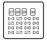
Instrument panel
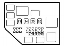
Engine compartment
| Fuses (type A) | |||
| Fuse number | Fuse name | Ampere rating [A] | Protected circuit |
| 1 | P/POINT | 15 | No circuit |
| 2 | . H−LP RH/H−LP LO RH | 10 | Right− hand headlight |
| 3 | 3. H−LP LH/H−LP LO LH | 10 | Left− hand headlight |
| 4 | ST | 30 | Starter system |
| 5 | AM2 | 15 | Starter system, SRS airbag system, multiport fuel injection system/sequential multiport fuel injection system, discharge warning system |
| 6 | HORN | 15 | Horn |
| 7 | EFI | 15 | Multiport fuel injection system/sequential multiport fuel injection system |
| 8 | DOME | 15 | Interior light, gauges of meters |
| 9 | SPARE | 15 | Spare |
| 10 | SPARE | 30 | Spare |
| 11 | GAUGE | 10 | Back−up lights, charging system, air conditioning system, gauges of meters |
| 12 | ACC | 15 | Cigarette lighter |
| 13 | A.C | 7,5 | Air conditioning system |
| 14 | WIPER | 20 | Windshield wipers and washer, rear window wipers and washer |
| 15 | ECU−IG | 7,5 | Anti−lock brake system, electric cooling fan |
| 16 | D/L | 25 | Power door lock system |
| 17 | ECU-D | 7,5 | SRS airbag system |
| 18 | OBD | 7,5 | On−board diagnosis system |
| 19 | TAIL | 10 | Tail lights, parking lights, license plate lights, illuminations |
| 20 | FOG | 15 | No circuit |
| 21 | HAZ | 10 | Turn signal lights, emergency flashers |
| 22 | STOP | 10 | Stop lights, high mounted stop light, anti−lock brake system, shift lock system, multiport fuel injection system/sequential multiport fuel injection system |
| Fuses (type B) | |||
| 23 | HTR SUB2 | 50 | No circuit |
| 24 | HTR SUB1 | 50 | Air conditioning system |
| 25 | RDI | 30 | Electric cooling fan |
| 26 | . CL−ACT2 | 30 | No circuit |
| 27 | AM1 | 40 | “ACC”, “GAUGE”, “WIPER”, and “ECU−IG” fuses |
| 28 | POWER | 30 | No circuit |
| 29 | HTR | 40 | Air conditioning system |
| 30 | DEF | 30 | Rear window defogger system |
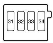
| Fuse (type C) | |||
| 31 | MAIN | 60 | “EFI”, “DOME”, “HORN”, “ST”, “AM2”, “H−LP LH”, “H−LP RH”, “H−LP LH (HI)”, “H−LP RH (HI)”, “H−LP LH (LO)” and “H−LP RH (LO)” fuse |
| 32 | CL−ACT1 | 60 | No circuit |
| 33 | ALT | 12 | “ECU−B”, “TAIL”, “D/L”, “OBD”, “A.C”, “HTR”, “POWER”, “STOP” and “DEF” fuses |
| 34 | ABS | 60 | Anti−lock brake system |
WARNING: Terminal and harness assignments for individual connectors will vary depending on vehicle equipment level, model, and market.