Volkswagen Baywindow Bus (1972) – fuse box diagram
Year of production: 1972
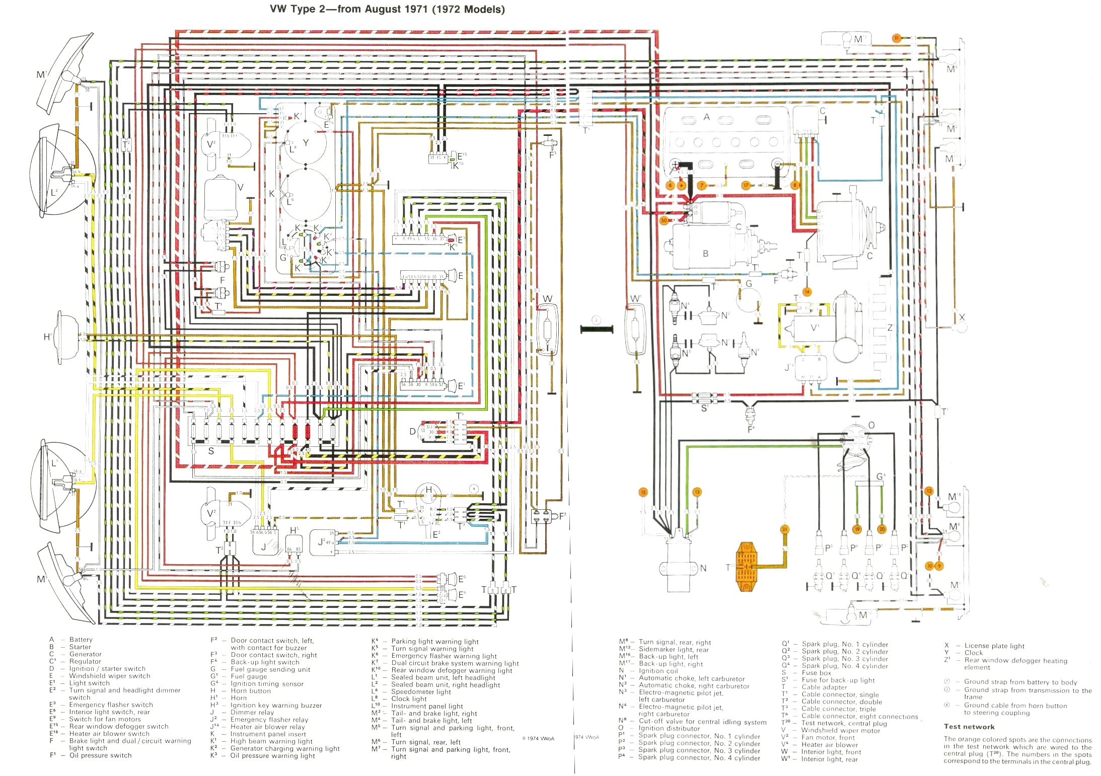
Wiring diagrams (1972 models) (411 937 505C)
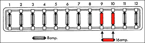
Fuse box diagram
| No. |
A |
Protected Component |
| 1 | 8 | Tail light left, Sidemarker rear left |
| 2 | 8 | Parking light front left and right, Tail light right, Sidemarker rear right, License plate light |
| 3 | 8 | Right headlight |
| 4 | 8 | Left headlight |
| 5 | 8 | Right high beam |
| 6 | 8 | Left high beam, High beam warning light |
| 7 | 8 | Fresh air fans |
| 8 | 8 | Interior light front, Emergency flasher, Turn signals |
| 9 | 16 | Accessory, Door buzzer, Interior light rear |
| 10 | 16 | Windshield wipers |
| 11 | 8 | Rear defogger, Oil warning light, Alternator light, Turn signal warning light, Gas gauge, |
| 12 | 8 | Horn, Brake lights, Brake warning light |
The owner’s manuals aren’t clear which fuses are 8A and which are 16A and it varies from year to year. Bentley is even less clear and there is a mistake in the manual but the color wiring diagrams explain which fuses protection which circuits.
- There are twelve fuses in fuseboxes of 70-79 models but only 10 in the 68-69 models.
- 68-69 models only use 8A fuses.
- Accessory means radio in most cases but can also mean gas heater in addition.
- Fresh air fans were mainly available on non-US models for defogging the front windshield.
WARNING: Terminal and harness assignments for individual connectors will vary depending on vehicle equipment level, model, and market.