Chevrolet Cobalt (2005 – 2010) – fuse box diagram
Year of production: 2005, 2006, 2007, 2008, 2009, 2010
Passenger Compartment Fuse Box
The floor console fuse block is located on the passenger side of the floor console behind the forward panel. The panel has three clips. Pull the panel to disconnect the three clips, and access the fuses.
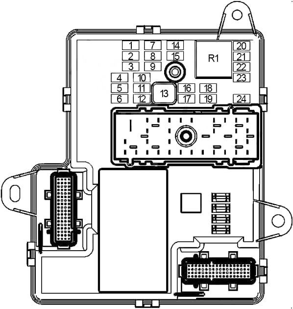
| No. |
A |
Protected Component |
| 1 | 10 | Engine Control Module (ECM), Transmission Control Module (TCM), Powertrain Control Module (PCM (2.2L – LSJ)) |
| 2 | 10 | ’08-’10: Vehicle Communication Interface Module (VCIM), Digital Radio Receiver (DRR) |
| 10 | ’05-’07: Inflatable Restraint Sensing and Diagnostic Module (SDM), Body Control Module (BCM) | |
| 3 | 15 | ’06-’10: Radio, Remote Control Door Lock Receiver (RCDLR) |
| 10 | ’05: Radio, Remote Control Door Lock Receiver (RCDLR) | |
| 4 | 2 | Steering Wheel Controls |
| 5 | 10 | Interior Lamps Relay |
| 6 | 15 | Power Door Lock (DOOR LOCK PCB Relay, DOOR UNLOCK PCB Relay, DR DOOR UNLOCK PCB Relay, INT LIGHT PCB Relay) |
| 7 | 2 | Electronic Power Steering Control Module (PSCM), Steering Wheel Controls (Left) |
| 8 | – | – |
| 9 | 2 | – |
| 10 | – | – |
| 11 | 20 | – |
| 12 | 15 | Sunroof Switch, Inside Rearview Mirror |
| 13 | 30 | Driver Window Switch, Front Passenger Window Switch |
| 14 | 10 | Clutch Pedal Start Switch (M/T), Instrument Panel Cluster (IPC), Heated Seat Switches, HVAC Control Module, Inflatable Restraint Passenger Air Bag On/Off Indicator, Stop Lamp/TCC Switch (’05-’07) |
| 15 | 10 | Windshield Wiper/Washer Switch, Turbocharger Boost Gauge (2.0L Turbo – LNF) |
| 16 | 10 | – |
| 17 | 10 | Inflatable Restraint Front Passenger Presence System (PPS) Module, Inflatable Restraint Sensing and Diagnostic Module (SDM) |
| 18 | 20 | – |
| 19 | – | – |
| 20 | 10 | HVAC Control Module, Theft Deterrent Control Module |
| 21 | 10 | ’05-’07: Stop Lamp Switch |
| 22 | 2 | Ignition Switch |
| 23 | 10 | Instrument Panel Cluster (IPC) |
| 24 | 20 | Audio Amplifier |
| Relay | ||
| R1 | Blower Motor | |
| Relay (Non-Serviceable) | ||
| R2 | Power Door Lock (Lock) | |
| R3 | Power Door Lock (Unlock) | |
| R4 | Driver Door Lock Actuator (Unlock) | |
| R5 | Interior Lamps | |
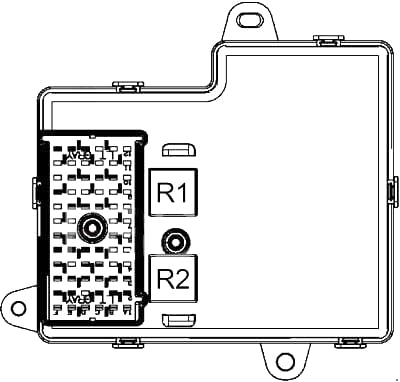
| No. |
Relay |
| R1 | Accessory (Power Window, Sunroof, Heated Seat, Windshield Wiper/Washer Switch) |
| R2 | Run (Heating Ventilation Air Conditioning (HVAC)) |
Engine Compartment Fuse Box
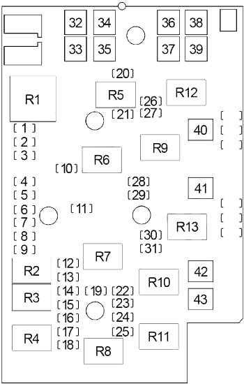
| No. |
A |
Protected Component |
| 1 | 20 | TRUNK PCB Relay, Driver and Passenger Heated Seat Modules |
| 2 | – | – |
| 3 | – | – |
| 4 | 10 | ’08-’10: Inflatable Restraint Sensing and Diagnostic Module (SDM), Body Control Module (BCM) |
| 10 | ’05-’07: Vehicle Communication Interface Module (VCIM), Digital Radio Receiver | |
| 5 | 20 | ’08-’10: Electronic Brake Control Module (EBCM) |
| 6 | 20 | ’08-’10: Cigar Lighter, Auxiliary Power Outlet, Data Link Connector (DLC (’05-)) |
| 15 | ’05-’07: Cigar Lighter, Data Link Connector (DLC) | |
| 7 | 5 | Outside Rearview Mirror Switch |
| 8 | 15 | ’08-’10: Data Link Connector (DLC) |
| 20 | ’05-’07: Heated Seat Module | |
| 9 | 10 | Evaporative Emission (EVAP) Canister Vent Solenoid |
| 10 | 25 | Windshield Wiper (Wiper On/Off Relay) |
| 11 | 10 | ’08-’10: Body Control Module (BCM), License Lamps, Marker Lamps, Park/Turn/DRL Signal Lamps, Tail/Stop and Turn Signal Lamps |
| 15 | ’05-’07: Body Control Module (BCM), License Lamps, Marker Lamps, Park/Turn Signal Lamps, Tail/Stop and Turn Signal Lamps Lamp | |
| 12 | 20 | Body Control Module (BCM) |
| 13 | 10 | A/C Compressor Clutch |
| 14 | 10 | Engine Control Module (ECM), Transmission Control Module (TCM), Center High Mounted Stop Lamp (CHMSL) |
| 15 | 2.0L (LJS): After Cooling Pump | |
| 15 | 10 | Electronic Brake Control Module (EBCM) |
| 16 | – | – |
| 17 | 15 | Engine Control Module (ECM), Transmission Control Module (TCM), Supercharger Boost Control Solenoid (2.0L – LSJ), Powertrain Control Module (PCM) (2.0L – LSJ) |
| 18 | 10 | Back Up Lamp Switch (M/T), Park Neutral Position (PNP) Switch (A/T) |
| 19 | 20 | Engine Control Module (ECM) |
| 20 | 10 | ’08-’10: Daytime Runnig Light |
| 21 | 15 | Fuel Pump and Sender Assembly |
| 22 | 10 | Evaporative Emission (EVAP) Canister Purge Solenoid, Heated Oxygen Sensors (HO2S), Mass Air Flow (MAF)/Intake Air Temperature (IAT) Sensor, Clutch Pedal Position (CPP) Switch |
| 23 | 10 | 2.0L Turbo (LNF): Turbocharger Wastegate Solenoid, Turbocharger Bypass Valve Solenoid, Camshaft Position (CMP) Actuator Solenoid – Intake, Camshaft Position (CMP) Actuator Solenoid – Exhaust |
| 24 | 15 | ’08-’10: Fuel Injectors, Ignition Coil/Modules |
| 10 | ’05-’07: Fuel Injectors, Ignition Coil/Modules | |
| 25 | 10 | ’06-’10: Secondary Air Injection (AIR) Solenoid |
| 26 | 15 | Front Fog Lamps |
| 27 | 10 | Horn |
| 28 | 10 | Right Headlamp (High Beam) |
| 29 | 10 | Left Headlamp (High Beam) |
| 30 | 10 | Right Headlamp (Low Beam) |
| 31 | 10 | Left Headlamp (Low Beam) |
| 32 | 60 | Electronic Power Steering (EPS) Control Module (PSCM) |
| 33 | 40 | ’06-’10: Secondary Air Injection (AIR) Pump Relay |
| 34 | – | – |
| 35 | 40 | ’08-’10: Electronic Brake Control Module (EBCM) |
| 50 | ’05-’07: Electronic Brake Control Module (EBCM) | |
| 36 | 30 | Blower Motor Relay |
| 37 | 40 | Fuse: “20”, “21”, “22”, 23″, “24” |
| 38 | – | – |
| 39 | – | – |
| 40 | 40 | Rear Window Defogger Relay |
| 41 | 30 | Cooling Fan Relay (No.2) |
| 42 | 30 | Starter Relay |
| 43 | 30 | Cooling Fan Relay (No.1) |
| Relay | ||
| R1 | Secondary Air Injection (AIR) Pump | |
| R2 | A/C Compressor Clutch | |
| R3 | Engine Control Module (ECM), Transmission Control Module (TCM), Center High Mounted Stop Lamp (CHMSL) | |
| 2.0L (LJS): After Cooling Pump | ||
| R4 | Ignition (RUN/CRNK) | |
| R5 | Fuel Pump | |
| R6 | Wiper (On/Off) | |
| R7 | Cooling Fan (No.2) | |
| Cooling Fans | ||
| R8 | Engine Control Module (ECM) | |
| R9 | Wiper (High/Low Speed) | |
| R10 | Starter | |
| R11 | Cooling Fan (No.1) | |
| R12 | Rear Window Defogger | |
| R13 | Secondary Air Injection (AIR) Solenoid | |
| Cooling Fan (No.2) | ||
WARNING: Terminal and harness assignments for individual connectors will vary depending on vehicle equipment level, model, and market.