Mercedes E Class w210 – E320T – fuse box diagram
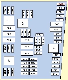
Fuse box – front (A 210 545 27 00)
| Function | Fuse number |
| ABS/ESP | 19,(11)* |
| Adjustable mirror, driver’s side | 16,(3)* |
| Adjustable mirror, passenger side | (1,3)* |
| Adjustable steering column | (8,9,13,14)* |
| ADS (SE) | 4 |
| Airbag systems | 10,13 |
| Anti-thef alarm system (SE) | 41,(5,11,19)* |
| Autom. comfort seat belt (SE) | 12 |
| Autom. dimming ext. mirror (SE) | (4)* |
| Autom. dimming int. mirror (SE) | (4)* |
| Autom. temperature control | 4,7 |
| Blower motor AC | 4,7 |
| Central locking system | 16,41,(1,4,5,19)* |
| Cigar lighter | 2 or 5 |
| COMAND (SE) | (5)* |
| Conveniece locking | 16,41,(1,4,19)* |
| Cooler box (SE) | (10)* |
| Coutesy lights | 16,18,(1,2,19)* |
| Dome lights | (3,4,19)* |
| Driver’s power window | 16,(3)* |
| E-Call | (15)* |
| Engine fan | 20 |
| Engine residual heat system | 4,7,(5,19)* |
| Fanfare | 40,41 |
| Folding exterior mirror (SE) | 14 |
| Fuel pump | (6)* |
| Garage door opener | (4)* |
| Glove compartment light | 3 |
| Hazard warning flasher | 41 |
| Headlamp flasher | 3,41 |
| Headlamp range Xenon (SE) | 15 |
| Headlamp washer system (SE) | 41,45 |
| Heated mirror, driver’s side | 16 |
| Heated mirror, passeneger side | (1)* |
| Heated rear window | 41,(19)* |
| Heated booster (SE) | 15 |
| Instrument cluster | 4,7 |
| Language control system | 4,7,10(15)* |
| Locking check – back | 41,(5,19)* |
| Make-up mirrors | (4)* |
| Multi-function steering wheel | 10 |
| Parktronic system (SE) | 15 |
| Passenger side power window | (1,3)* |
| Power window, rear left | 18,(3)* |
| Power window, rear right | (2,3)* |
| Radio | (5)* |
| Rain sensor (SE) | (4)* |
| Rear head release | 41,(5,19)* |
| Rear plug socket (T-model) | 11 |
| Rear reading lamp (SE) | 11,(3)* |
| Rear window wiper (T-model) | 12,41,44,(19)* |
| Remote trunk release | (3,5,19)* |
| Reverse gear recognition | (3)* |
| Seat adjustment Memory | 16,(1,8,9,13,14)* |
| Seat heater (SE) | 12,(17,18)* |
| Seat ventilation (SE) | (3)* |
| Sound system | (16)* |
| Steering lock | 9 |
| Sun blind for rear window (SE) | 12 |
| Tail gate closing assist (T-model) | (5,7,19)* |
| Tekephone systems (SE) | (15)* |
| Tilting/sliding roof (SE) | 41,(4)* |
| Tire pressure monitor (SE) | 14,(15)* |
| Trailer power supply (SE) | (12)* |
| Trunk light | (3,19)* |
| Turn signal, t.s. indicator lamp | 3,41 |
| TV/Video (SE) | (10)* |
| Washer water heater | 42 |
| Windshield washer system | 41,43,(5,19)* |
| Wiper system | 3,41,44 |
* NOTE:
Fuses in brackets (thin lettering) are to be found the rear seat.
Further fuses are to be found in cockpit near the light switch.
The fuse extractor is to be found in the vehicle tool kit.
(SE) = function of a special equipment them.
| Fuse rating | Colour | Fuse number |
| 7,5 | brown | 23,24,42,(11,15)* |
| 10 | red | 4,10,12,13,40,43,(3,10)* |
| 15 | blue | 2,3,5,7,9,11,14,15,41 |
| 20 | yellow | 16,17,18,(1,2,7,17,18)* |
| 25 | natural | 25,(4,5,6,8,9,12,13,14,16)* |
| 30 | green | 20 (E430),45 |
| 40 | orange | 19,44,(19)* |
| 50 | red | 20 (E280,E320) |
Fuse extractor in tool kit (210 545 02 00)
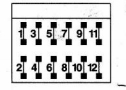
| Fuse | Ampere rating | Colour | Function |
| 1 | — | — | Not assigned |
| 2 | 15 | light blue | Brakelamp /(Tempomat-cruise control) |
| 3 | 7,5 | brown | Right high beam |
| 4 | 15 | light blue | Reversing lamp/turn signallamp _ (Control, rearwiper/anli-dazzle rearviewmirror Control, parking aid) |
| 5 | 7,5 | brown | Left high beam |
| 6 | 15 | light blue | Right low beam |
| 7 | 7,5 | brown | Right parking/taillamp side maker |
| 8 | 15 | light blue | Left low beam |
| 9 | 15 | light blue | Fog lamp |
| 10 | 7,5 | brown | Left parking/tail lamp side marker |
| 11 | 7,5 | brown | Licence plate/instrument cluster lighting/symbol lighting |
| 12 | 7,5 | brown | Rear fog lamp |
| Electrical accessories written in brackets are special options | |||
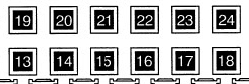
Fuses in battery box (A 210 545 29 00)
| Function | Fuse number |
| Adjustable mirrors | 1,3,(16)* |
| Adjustable steering column | 8,9,13,14 |
| ADS (SE) | (4)* |
| Anti-thef alarm system (SE) | 5,11,19,(41)* |
| Autom. dimming ext. mirror (SE) | 4 |
| Autom. dimming int. mirror (SE) | 4 |
| Central locking system | 1,4,5,19,(16,41)* |
| COMAND (SE) | 5 |
| Conveniece locking | 1,4,19,(16,41)* |
| Courtesy lights | 1,2,19,(16,18)* |
| Dome lights | 3,4,19 |
| E-Call | 15 |
| Fuel pump | 6 |
| Garage door opener | 4 |
| Heated mirror, passeneger side | 1 |
| Heated rear window | 19,(41)* |
| Language control system | 15,(4,7,10)* |
| Locking check-back | 5,19,(41)* |
| Make-up mirrors | 4 |
| Power windows | 1,2,3,(16,18)* |
| Radio | 5 |
| Rain sensor (SE) | 4 |
| Rear head release | 5,19,(41)* |
| Rear reading lamp (SE) | 3,(11)* |
| Rear window wiper (T-model) | 19,(12,41,44)* |
| Remote trunk release | 3,5,19 |
| Reverse gear recognition | 3 |
| Seat adjustment Memory | 1,8,9,13,14,(16)* |
| Seat heater (SE) | 17,18,(12)* |
| Seat ventilation (SE) | 3 |
| Sound system | 16 |
| Tail gate closing assist (T-model) | 5,7,19 |
| Telephone systems (SE) | 15 |
| Tilting/sliding roof (SE) | 4,(41)* |
| Tire pressure monitor (SE) | 15,(14)* |
| Trailer power supply (SE) | 12 |
| Trunk light | 3,19 |
| TV/Video (SE) | 10 |
| Windshield washer system | 5,19,(41,43)* |
*NOTE:
Fuses in brackets (thin lettering)are to be found in the front fuse box.
Further fuses are to be found in the coockpit near the light switch.
The fuse extractor is to be found in the vehicle tool kit.
(SE)-function of a special equipment item.
| Ampere rating [A] | Colour | Fuse number |
| 7,5 | brown | 11,15,(23,24,42)* |
| 10 | red | 3,10,(4,10,12,13,40,43)* |
| 15 | blue | (2,3,5,7,9,11,14,15,41)* |
| 20 | yellow | 1,2,7,17,18,(16,17,18)* |
| 25 | natural | 4,5,6,8,9,12,13,14,16,(25)* |
| 40 | orange | 19,(19,44)* |
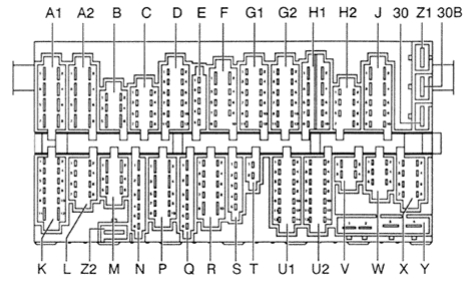
WARNING: Terminal and harness assignments for individual connectors will vary depending on vehicle equipment level, model, and market.