Citroen C1 mk2 (from 2014) – fuse box diagram
Year of production: 2014, 2015, 2016
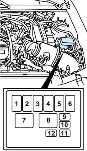
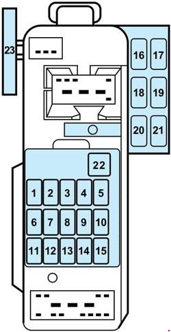
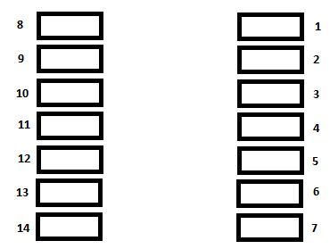
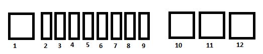
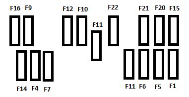
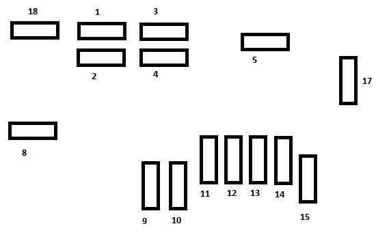
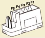
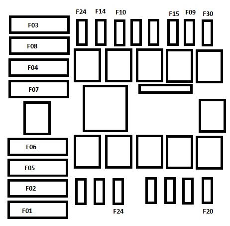
Fuse box under dashboard
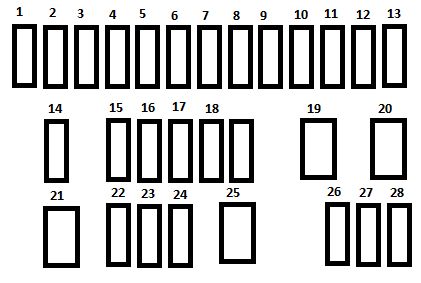
| Fuse | Ampere rating [A] | Functions |
| 1 | 5 | Fuel injection system, audio system, VSC system |
| 2 | 15 | Front and rear screenwasher |
| 3 | 5 | Main distribution unit, instrument panel, display screen, air conditioning, heated rear screen and door mirror heating, electric fabric roof, audio system |
| 4 | 5 | Electric power steering, Srop & Start |
| 5 | 15 | Rear wiper |
| 6 | 5 | Cooling fan, ABS system ESP, VS system |
| 7 | 25 | Front wiper |
| 8 | 10 | Heated door mirrors |
| 9 | 15 | 12 V socket (120 W max) |
| 10 | 7,5 | Door mirrors, audio system, Start & Start, instrument panel, dusplay screen |
| 11 | 5 | Steering lock, fuel injection system, electronic gearbox |
| 12 | 7,5 | Airbags |
| 13 | 5 | Instrument panel, display screen, Stop & Start |
| 14 | 15** | Steering, fuel injection system, brake lamps |
| 7,5* | ||
| 15 | 7,5** | Fuel injection syste, Stop&Start |
| 10* | ||
| 16 | 7,5 | Engine diagnosis |
| 17 | 10 | Brake lamps, third brake lamp, fuel injection system, ABS system, VSC system, electronic gearbox, keyless entry and starting system |
| 18 | 10 | Sidelamps, number plate lamps, rear foglamps, front foglamps, rear lamps, lighting dimmer |
| 19 | 40 | Klimatyzacja |
| 20 | 40 | Air conditioning, engine self-diagnosis, sidelamps, number plate lamps, rear foglamp, front foglamps, rear lamps, lighting dimmer, brake lamps, third brake lamp, fuel injection system, ABS system, VSC system, electronic gearbox, “Keyless entry and starting” system, electric windows |
| 21 | 30 | Fuel injection system, Stop & Start, main distribution unit |
| 22** | 7,5 | Fuel injection system |
| 23** | 20 | Fuel injection system, Stop & Start |
| 24 | 25 | Main distribution unit |
| 25 | 30 | Electric windows |
| 26 | 25 | Electric windows |
| 27 | 10 | Air conditioning |
| 28 | 5 | Rear foglamp |
* VTi 82 engine
** VTi 68 engine
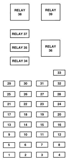
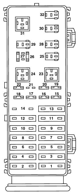
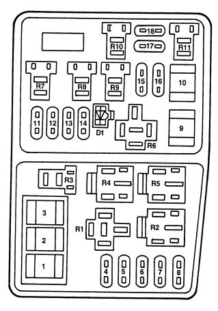
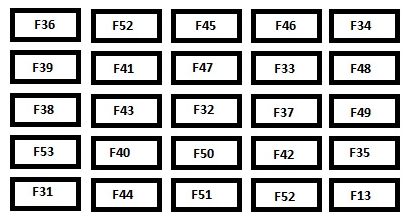
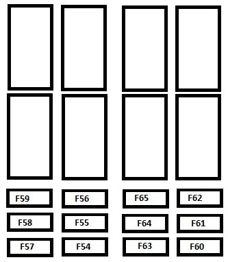
Fuse box in engine compartment
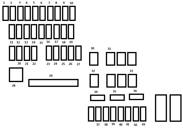
| Fuse | Ampere rating [A] | Functions |
| 1 | 10 | Right hand dipped beam |
| 2 | 10 | Left hand dipped beam, headlamp adjustment |
| 3 | 7,5 | Right hand main beam |
| 4 | 7,5 | Left han main beam |
| 5* | 15 | Fuel injection system |
| 6* | 7,5 | Fuel injection system |
| 7* | 15 | Fuel injection system |
| 8* | 7,5 | Cooling fan |
| 9 | 7,5 | Air conditioning |
| 10** | 7,5 | Fuel injection system, brake lamps, third brake lamp |
| 11 | 5 | Courtesy lamp, boot lamp |
| 12 | 10 | Direction indicators, hazard warning lamps, instrument panel, display screen |
| 13 | 10 | Horn |
| 14 | 30 | Distribution units |
| 15** | 7,5 | Electronic gearbox |
| 16 | 7,5 | Fuel injection system |
| 17 | 7,5 | Keyless injection system, cooling fan |
| 18** | 7,5 | Battery |
| 19 | 25 | Fuel injection system, cooling fan |
| 20 | 30 | Starter motor |
| 21 | 7,5 | Steering lock |
| 22 | 25 | Front lamps |
| 23 | 7,5 | Fuel injection system |
| 24 | 7,5 | Fuel injection system, starter motor, electronic gearbox, Stop & Start |
| 25 | 15 | Audio system, “Keyless entry and starting” system |
| 26 | 7,5 | Instrument panel, display screen |
| 27 | 7,5 | VSC system |
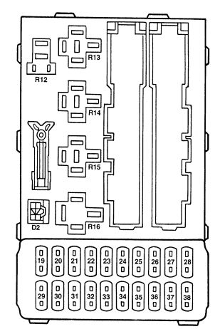
| 28 | 60 | Passenger compartment fusebox |
| 29** | 125 | Heated rear screen and door mirror heating, electric fabric roof, ABS system, VSC system, cooling fan, front foglamps, LED daytime running lamps |
| 30 | 50 | Electric gearbox |
| 40 | Stop & Start | |
| 31 | 50 | Power steering |
| 32 | 50* | Cooling fan |
| 30 | ||
| 40 | ||
| 33 | 50 | ABS system, VSC system |
| 34 | 10 | Spare fuse |
| 35 | 20 | Spare fuse |
| 36 | 30 | Spare fuse |
| 37 | 20 | Heated rear screen and door mirror heating |
| 38 | 30 | ABS system, VSC system |
| 39 | 7,5 | Front foglamps, instrument panel, dispaly screen |
| 40 | 7,5 | LED daytime running lamps |
| 41 | — | Not used |
| 42 | 20 | Electric fabric roof |
| 43 | — | Not used |
* VTi 82 engine
** VTi 68 engine
WARNING: Terminal and harness assignments for individual connectors will vary depending on vehicle equipment level, model, and market