Volkswagen Passat B7 (2010 – 2014) – fuse box diagram

Volkswagen Passat B7 (2010 – 2014) – fuse box diagram

Year of production: 2010, 2011, 2012, 2013, 2014

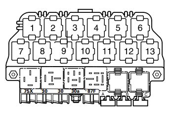
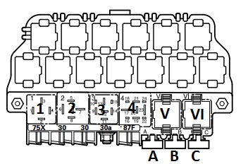
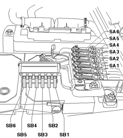
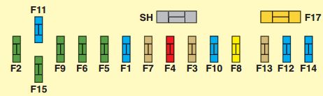
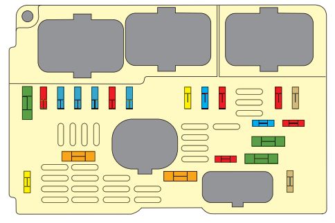
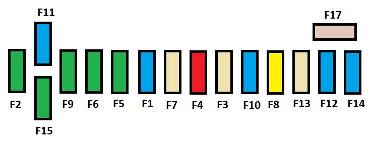
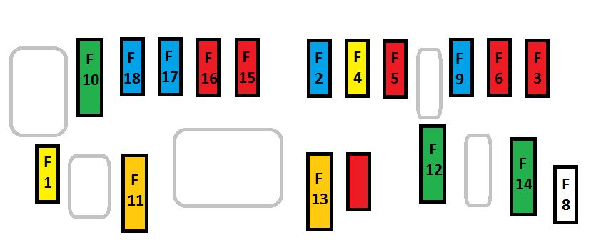
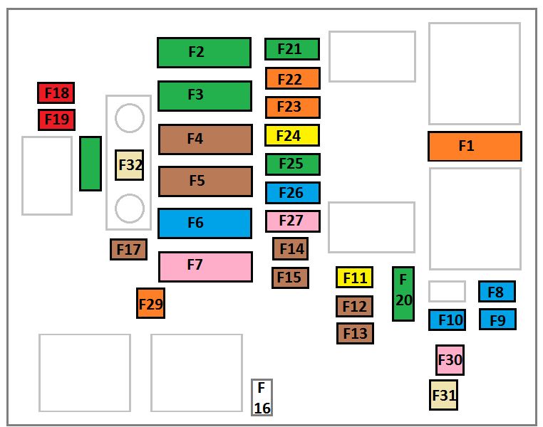
Fuse panel B (under hood)

Number Designation in Wiring Diagram Nominal Value Function/Component Terminal
F1 -Fuse panel B -SB1- Not used
F2 -Fuse 2 on fuse panel B -SB2- 15 -Engine control module -J623- 87a
F3 -Fuse 3 on fuse panel B -SB3- 30 -Reducing agent reservoir sensor -G697- 2 Reducing agent reservoir processing unit – G698- 2 Coolant fan control module -J293- Wastegate bypass regulator valve -N75- Positive crankcase ventilation heating element – N79-Reducing agent reversing valve -N473- 2 87a
F4 -Fuse 4 on fuse panel B -SB4- 15 -NOx sensor -G295-2 Oxygen sensor 1 before catalytic converter -GX10-Oxygen sensor 2 before catalytic converter -GX11- 1 Oxygen sensor heater -Z19-Oxygen sensor 2 heater -Z28-1 NOx sensor control module 2 -J881- 2 87a
20
F5 -Fuse 5 on fuse panel B -SB5- 5 -Mass air flow sensor -G70-2 Oxygen sensor 1 after catalytic converter -GX7-Oxygen sensor 2 after catalytic converter -GX8-1 Heater for oxygen sensor 1 after catalytic converter -Z29-Heater for oxygen sensor 2 after catalytic converter -Z30- 1 87a
10
15
20
F6 -Fuse 6 on fuse panel B -SB6- 10 -EVAP canister purge regulator valve 1 -N80- 1 Secondary air injection solenoid valve – N112- 3 Camshaft adjustment valve 1 -N205-1 Fuel pressure regulator valve -N276- 1 Exhaust camshaft adjustment valve 1 -N318-1 Fuel pump relay -J17-3 Secondary air pump 87a
20
F7 F7 -Fuse 7 on fuse panel B -SB7- 20 -Ignition coil 1 with power output stage -N70-Ignition coil 2 with power output stage – N127-Ignition coil 3 with power output stage -N291-Ignition coil 4 with power output stage -N292-Ignition coil 5 with power output stage -N323- 1 Ignition coil 6 with p 87a
30
F8 F8 -Fuse 8 on fuse panel B -SB8- 10 -EVAP canister purge regulator valve 1 -N80- 1 Camshaft adjustment valve 1 -N205-1 Exhaust camshaft adjustment valve 1 -N318-1 Reducing agent heater control module – 87a
30
F9 F9 -Fuse 9 on fuse panel B -SB9- 5 -Brake lamp switch -F-Rear air distribution motor position sensor -G478- 87a
F10 F10 -Fuse 10 on fuse panel B -SB10- 5 -Mass air flow sensor -G70-1 Fuel pump relay -J17-2 Automatic glow time control module -J179- 2 87a
F11 F11 -Fuse 11 on fuse panel B -SB11- 30 DSG transmission Mechatronic -J743- 1 30a
F12 F12 -Fuse 12 on fuse panel B -SB12- 15 Coolant pump -VX20- 1 87a
F13 F13 -Fuse 13 on fuse panel B -SB13- 30 -Radio -R-Radio/navigation display unit control module -J503-External multimedia device interface -R215- 30a
F14 F14 -Fuse 14 on fuse panel B -SB14- 5 -Motronic engine control module power supply relay -J271- 1, 3 Terminal 30 power supply relay -J317- 2 Engine control module -J623- 30a
F15 F15 -Fuse 15 on fuse panel B -SB15- 20 -High tone horn -H2-Low tone horn -H7-Dual tone horn relay -J4- 30a
F16 F16 -Fuse 16 on fuse panel B -SB16- 40 -Amplifier -R12- 30a
F17 F17 -Fuse 17 on fuse panel B -SB17- 30 DSG transmission Mechatronic -J743- 2 30a
F18 F18 -Fuse 18 on fuse panel B -SB18- 5 Telephone transceiver -R36- 30a
F19 F19 -Fuse 19 on fuse panel B -SB19- 5 Vehicle electrical system control module -J519- (T52a/24) 30 Ref
F20 F20 -Fuse 20 on fuse panel B -SB20- 40 Wiper motor change-over relay -J368-Wiper motor change-over relay 2 -J369- 30
F21 F21 -Fuse 21 on fuse panel B -SB21- 40 Secondary air injection pump motor -V101- 3 Auxiliary heater heating element -Z35- (T3hr/1) 2 30a
F22 F22 -Fuse 22 on fuse panel B -SB22- 40 Auxiliary heater heating element -Z35- (T3hr/3) 2 30a
F23 F23 -Fuse 23 on fuse panel B -SB23- 50 Fuse 32 on fuse panel C -SC32-Fuse 33 on fuse panel C -SC33-Fuse 34 on fuse panel C – SC34- 30a
F24 F24 -Fuse 24 on fuse panel B -SB24- 50 Terminal 75 power supply relay 1 -J680-Fuse 40 on fuse panel C -SC40-Fuse 42 on fuse panel C -SC42- 30a
F25 F25 -Fuse 25 on fuse panel B -SB25- 40 Terminal 15 power supply relay 2 -J681- 30a
F26 F26 -Fuse 26 on fuse panel B -SB26- 50 Automatic glow time control module -J179- (T11a/11) 30a
F27 F27 -Fuse 27 on fuse panel B -SB27- 50 Coolant fan control module -J293- 30a
F28 F28 -Fuse 28 on fuse panel B -SB28- 40 Vehicle electrical system control module -J519- (T52a/1) 30a
F29 F29 -Fuse 29 on fuse panel B -SB29- 40 Vehicle electrical system control module -J519- (T52c/42) 30a
F30 F30 -Fuse 30 on fuse panel B -SB30- 40 ABS control module -J104- (T47/1) 30a
F31 F31 -Fuse 31 on fuse panel B -SB31- 30 ABS control module -J104- (T47/32) 30a
F32 F32 -Fuse 32 on fuse panel B -SB32- 40 Auxiliary heater heating element -Z35- (T3hr/2) 2 30a

1) Only for vehicles with a 3.6L gasoline engine and engine code CDVB

2) Only for vehicles with a 2.0L diesel engine and engine code CKRA

3) Only for vehicles with a 2.5L gasoline enigne and engine code CBUA


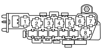
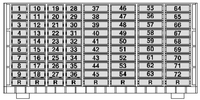
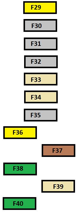
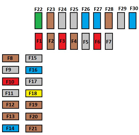
Fuse panel C (dashboard)
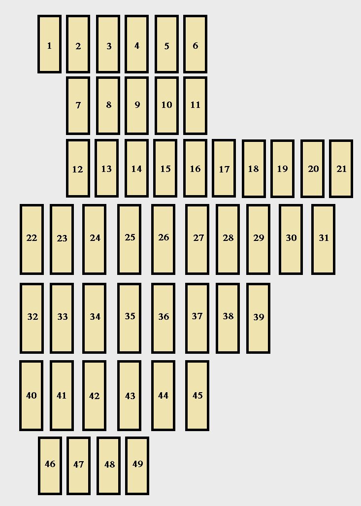
Volkswagen Passat B7 - fuse box - dashboard
Volkswagen Passat B7 – fuse box – dashboard
Number Designation in Wiring Diagram Ampere rating [A] Function/component Terminal
F1 Fuse 1 on fuse panel C -SC1- 7,5 Headlight DRLs, HID Adjuster motors, Whistler Radar Detector 15a
F2 Fuse 2 on fuse panel C -SC2- 15 Airbag control module -J234-, Front passenger airbag -disabled- indicator lamp -K145- 15a
F3 Fuse 3 on fuse panel C -SC3- 7,5 Light switch -E1- (T10h/4), Oil level thermal sensor -G266- (T6z/4), ABS control module -J104- (47/8), Instrument cluster control module -J285- (T32/31), Power steering control module -J500- (T6z/1) Data, Engine control module -J623- (T94/87), DSG transmission Mechatronic -J743- (T20e/13), Starter relay 1 -J906- (T7/1), Starter relay 2 -J907- (T9c/1) 15a
F4 Fuse 4 on fuse panel C -SC4 7,5 Back-up lamp switch -F4-, High pressure sensor -G65-, Air quality sensor -G238-, Garage door opener control module -J530-, Parallel parking assistance control module -J791-, 16-pin connector -T16- (diagnostic connector), Automatic dimming interior rearview mirror -Y7 -, Left washer nozzle heater -Z20-, Right washer nozzle heater -Z21- 15a
F5 Fuse 5 on fuse panel C -SC5- Not used
F6 Fuse 6 on fuse panel C -SC6- Not used
F7 Fuse 7 on fuse panel C -SC7- Not used
F8 Fuse 8 on fuse panel C -SC8- Not used
F9 – Fuse 9 on fuse panel C -SC9- Not used
F10 Fuse 10 on fuse panel C -SC10- Not used
F11 Fuse 11 on fuse panel C -SC11- Not used
F12 Fuse 12 on fuse panel C -SC12- 10 Light switch -E1- (T10h/8), Tiptronic switch -F189, Vehicle electrical system control module -J519- (T52c/1), Selector lever sensor system control module -J587, Electronic steering column lock control module -J764, 16-pin connector -T16- diagnostic connector (T16/16) 30a
F13 Fuse 13 on fuse panel C -SC13- 10 Instrument cluster control module -J285- (T32/32) 30a
F14 Fuse 4 on fuse panel C -SC14- Not used
F15 Fuse 15 on fuse panel C -SC15- 5 Electronic steering column lock control module -J764- 30a
F16 Fuse 16 on fuse panel C -SC16- 5 Data bus on board diagnostic interface -J533- (T20/1) 30a
F17 Fuse 17 on fuse panel C -SC17- 10 Steering column electronics control module -J527- (T16l/1) 30a
F18 Fuse 18 on fuse panel C -SC18- Not used
F19 Fuse 19 on fuse panel C -SC19- Not used
F20 Fuse 20 on fuse panel C -SC20- Not used
F21 Fuse 21 on fuse panel C -SC21- Not used
F22 Fuse 22 on fuse panel C -SC22- 30 28-pin connector -T28a/22- (right A-pillar), 28-pin connector -T28a/22- (right B-pillar) 30a
F23 Fuse 23 on fuse panel C -SC23- 30 Rear window defogger relay -J9-, Rear window defogger -Z1- 30a
F24 Fuse 24 on fuse panel C -SC24- 20 Fuel pump relay -J17-, Fuel pump control module -J538- (T10n/1), Transfer fuel pump -G6- 30a
30
F25 Fuse 25 on fuse panel C -SC25- 20 Climatronic control unit -J255- A/C control module -J301- Automatic transmission control module -J217-
F26 Fuse 26 on fuse panel C -SC26- 15 Rear lid remote lock key switch -E232-, Compass magnetic field sensor -G197-, Rain/light recognition sensor -G397-, Remote start system relay -J471-, Analog clock -Y 30
F27 Fuse 27 on fuse panel C -SC27 Not used
F28 Fuse 28 on fuse panel C -SC28- 30 Automatic transmission control module -J217- 15a
F29 Fuse 29 on fuse panel C -SC29- 20 Vehicle electrical system control module -J519- (T52b/1) 30a
F30 Fuse 30 on fuse panel C -SC30- 20 Vehicle electrical system control module -J519- (T52b/42) 30a
F31 Fuse 31 on fuse panel C -SC31- 30 28-pin connector -T28/22- (left A-pillar), 28-pin connector -T28b/22- (left B-pillar) 30a
F32 Fuse 32 on fuse panel C -SC32- 40 Trunk 12 V Plug [OEM-Fresh air blower control module -J126-], Fresh air blower -V2- 30a
F33 Fuse 33 on fuse panel C -SC33- 30 Front seat heating control module -J774- (T8z/3, T8z/6) 30a
F34 Fuse 34 on fuse panel C -SC34- 20 Power sunroof control module -J245-, (T16s/1) Sunroof motor -V1- 30a
F35 Fuse 35 on fuse panel C -SC35- 30 Driver seat lumbar support adjustment switch -E176-, Front passenger seat lumbar support adjustment switch -E177-, Driver seat lumbar support curvature adjustment motor -V125-, Front passenger seat lumbar support curvature adjustment motor -V126- 30a
F36 Fuse 36 on fuse panel C -SC36 Not used
F37 Fuse 37 on fuse panel C -SC37- Not used
F38 Fuse 38 on fuse panel C -SC38- Not used
F39 Fuse 39 on fuse panel C -SC39- Not used
F40 Fuse 40 on fuse panel C -SC40- 40 400W Inverter in Trunk [OEM- A/C control module -J301-], Fresh air blower -V2- 75a
F41 Fuse 41 on fuse panel C -SC41- Not used
F42 Fuse 42 on fuse panel C -SC42- 30 Cigarette lighter -U1-12 V socket 2 -U18 75a
F43 Fuse 43 on fuse panel C -SC43- Not used
F44 Fuse 44 on fuse panel C -SC44- Not used Fuse 44 on fuse panel C -SC44-
F45 Fuse 45 on fuse panel C -SC45- Not used
F46 Fuse 46 on fuse panel C -SC46- Not used
F47 – Fuse 47 on fuse panel C -SC47- Not used
F48 Fuse 48 on fuse panel C -SC48- Not used
F49 – Fuse 49 on fuse panel C -SC49- Not used

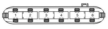
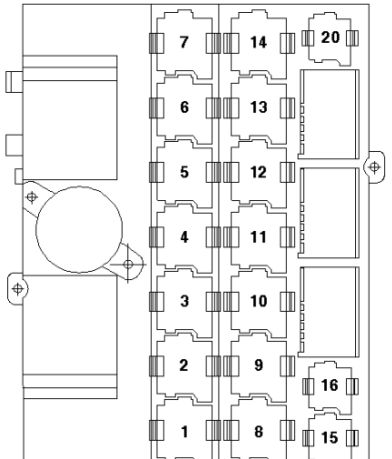
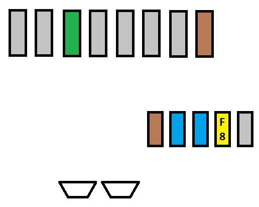
Fuse panel E (VR6 only)

Panel E is the one in the trunk with your battery on the VR6.

Number Designation in Wiring Diagram Ampere rating [A] Function/Component Terminal
F1 -Fuse panel B -SB1- Not used
F2 -Fuse 2 on fuse panel B -SB2- 15 -Engine control module -J623- 87a
30
F3 -Fuse 3 on fuse panel B -SB3- 30 -Reducing agent reservoir sensor -G697- 2, Reducing agent reservoir processing unit, G698- 2 Coolant fan control module -J293-, Wastegate bypass regulator valve -N75-, Positive crankcase ventilation heating element -, N79-Reducing agent reversing valve -N473- 2 87a
F4 -Fuse 4 on fuse panel B -SB4- 15 -NOx sensor -G295-2 Oxygen sensor 1 before catalytic converter -GX10-Oxygen sensor 2 before catalytic converter -GX11- 1 Oxygen sensor heater -Z19-Oxygen sensor 2 heater -Z28-1 NOx sensor control module 2 -J881- 2 87a
20
F5 -Fuse 5 on fuse panel B -SB5- 5 -Mass air flow sensor -G70-2 Oxygen sensor 1 after catalytic converter -GX7-Oxygen sensor 2 after catalytic converter -GX8-1 Heater for oxygen sensor 1 after catalytic converter -Z29-Heater for oxygen sensor 2 after catalytic converter -Z30- 1 87a
10
15
20
F6 -Fuse 6 on fuse panel B -SB6- 10 -EVAP canister purge regulator valve 1 -N80- 1 Secondary air injection solenoid valve – N112- 3 Camshaft adjustment valve 1 -N205-1 Fuel pressure regulator valve -N276- 1 Exhaust camshaft adjustment valve 1 -N318-1 Fuel pump relay -J17-3 Secondary air pump 87a
20
F7 F7 -Fuse 7 on fuse panel B -SB7- 20 -Ignition coil 1 with power output stage -N70-Ignition coil 2 with power output stage – N127-Ignition coil 3 with power output stage -N291-Ignition coil 4 with power output stage -N292-Ignition coil 5 with power output stage -N323- 1 Ignition coil 6 with p 87a
30
F8 F8 -Fuse 8 on fuse panel B -SB8- 10 -EVAP canister purge regulator valve 1 -N80- 1 Camshaft adjustment valve 1 -N205-1 Exhaust camshaft adjustment valve 1 -N318-1 Reducing agent heater control module – J891- 2 Leak detection pump -V144- 1 87a
30
F9 F9 -Fuse 9 on fuse panel B -SB9- 5 -Brake lamp switch -F-Rear air distribution motor position sensor -G478- 87a
F10 F10 -Fuse 10 on fuse panel B -SB10- 5 -Mass air flow sensor -G70-1 Fuel pump relay -J17-2 Automatic glow time control module -J179- 2 87a
F11 F11 -Fuse 11 on fuse panel B -SB11- 30 DSG transmission Mechatronic -J743- 1 30a
F12 F12 -Fuse 12 on fuse panel B -SB12- 15 Coolant pump -VX20- 1 87a
F13 F13 -Fuse 13 on fuse panel B -SB13- 30 -Radio -R-Radio/navigation display unit control module -J503-External multimedia device interface -R215- 30a
F14 F14 -Fuse 14 on fuse panel B -SB14- 5 -Motronic engine control module power supply relay -J271- 1, 3 Terminal 30 power supply relay -J317- 2 Engine control module -J623- 30a
F15 F15 -Fuse 15 on fuse panel B -SB15- 20 -High tone horn -H2-Low tone horn -H7-Dual tone horn relay -J4- 30a
F16 F16 -Fuse 16 on fuse panel B -SB16- 40 -Amplifier -R12- 30a
F17 F17 -Fuse 17 on fuse panel B -SB17- 30 DSG transmission Mechatronic -J743- 2 30a
F18 F18 -Fuse 18 on fuse panel B -SB18- 5 -Telephone transceiver -R36- 30a
F19 F19 -Fuse 19 on fuse panel B -SB19- 5 Vehicle electrical system control module -J519- (T52a/24) 30 Ref.
F20 F20 -Fuse 20 on fuse panel B -SB20- 40 Wiper motor change-over relay -J368-Wiper motor change-over relay 2 -J369- 30a
F21 F21 -Fuse 21 on fuse panel B -SB21- 40 Secondary air injection pump motor -V101- 3 Auxiliary heater heating element -Z35- (T3hr/1) 2 30a
F22 F22 -Fuse 22 on fuse panel B -SB22- 40 Auxiliary heater heating element -Z35- (T3hr/3) 2 30a
F23 F23 -Fuse 23 on fuse panel B -SB23- 50 Fuse 32 on fuse panel C -SC32-Fuse 33 on fuse panel C -SC33-Fuse 34 on fuse panel C – SC34- 30a
F24 F24 -Fuse 24 on fuse panel B -SB24- 50 Terminal 75 power supply relay 1 -J680-Fuse 40 on fuse panel C -SC40-Fuse 42 on fuse panel C -SC42- 30
F25 F25 -Fuse 25 on fuse panel B -SB25- 40 Terminal 15 power supply relay 2 -J681- 30a
F26 F26 -Fuse 26 on fuse panel B -SB26- 50 Automatic glow time control module -J179- (T11a/11) 30a
F27 F27 -Fuse 27 on fuse panel B -SB27- 50 Coolant fan control module -J293- 30a
F28 F28 -Fuse 28 on fuse panel B -SB28- 40 Vehicle electrical system control module -J519- (T52a/1) 30a
F29 F29 -Fuse 29 on fuse panel B -SB29- 40 Vehicle electrical system control module -J519- (T52c/42) 30a
F30 F30 -Fuse 30 on fuse panel B -SB30- 40 ABS control module -J104- (T47/1) 30a
F31 F31 -Fuse 31 on fuse panel B -SB31- 30 ABS control module -J104- (T47/32) 30a
F32 F32 -Fuse 32 on fuse panel B -SB32- 40 Auxiliary heater heating element -Z35- (T3hr/2) 2 30a

1) Only for vehicles with a 3.6L gasoline engine and engine code CDVB

2) Only for vehicles with a 2.0L diesel engine and engine code CKRA

3) Only for vehicles with a 2.5L gasoline enigne and engine code CBUA


WARNING: Terminal and harness assignments for individual connectors will vary depending on vehicle equipment level, model, and market.

Volkswagen Passat B5 FL (2000 – 2005) – fuse box diagram

Volkswagen Passat B5 FL (2000 – 2005) – fuse box diagram

Year of productions: 2000, 2001, 2002, 2003, 2004, 2005


Relay arrangement on thirteenfold auxiliary relay panel above relay panel

Volkswagen Passat B5 FL - fuse box - auxiliary relay panel
Volkswagen Passat B5 FL – fuse box – auxiliary relay panel
Relay Description
1 Coolant Fan Control (FC)‐A/C Relay (373)
2 Sun-Roof Relay (79)
3 A/C Clutch Relay (267), A/C Clutch Relay (384)
4 Daytime Running Lights Change‐Over Relay (173)
5 Taxi Alarm Relay, High Beam Headlight Relay, Emergency Flasher Relay
6 Selector Lever Light Relay
7 Fog Light Relay (381)
8 Control Module for Multi‐function steering wheel (451), Control Module for Multi‐function steering wheel (452)
9 Control Module for Multi‐function steering wheel (451), Control Module for Multi‐function steering wheel (452)
10 Brake Booster Relay (373)
11 Taxi Alarm Relay Emergency Flasher Relay (200)
12 Dual Horn Relay (53) Taxi Alarm Relay
13 Park/Neutral Position (PNP) Relay (175), Starting Interlock Relay‐Clutch Position (53)

Fuses at thirteenfold relay-panel

Fuse Description Ampere rating [A]
A Fuse for Taxi 25
B Fuse for Taxi 20
High Beam Headlight left 10
C Fuse for Brake System Vacuum Pump 15
D Fuse for Power Outlet (12 V) Rear Console 20
E Fuse for Taxi 5
High Beam Headlight right 10

Relay locations on relay panel

Volkswagen Passat B5 FL - fuse box - auxiliary relay panel
Volkswagen Passat B5 FL – fuse box – auxiliary relay panel
Relay Description
1 Dual Horn Relay (53)
2 Load Reduction Relay (370)
3 Free
4 Fuel Pump (FP) Relay (372) (409)
V Wiper/Washer Intermittent Relay (377) (389), Wiper/Washer Intermittent Relay/Rainsensor (192)
VI Wiper/Washer Intermittent Relay (377) (389), Wiper/Washer Intermittent Relay/Rainsensor (192)

Fuses on relay panel

Fuses Description Ampere rating [A]
A Fuse for 12v socket I in luggage compartment 20
B Fuse for 12v socket II in luggage compartment 20
C Fuse for Taxi 10

Relay arrangements on eightfold (eight posion) auxiliary relay panel behind relay panel

Volkswagen Passat B5 FL - fuse box - auxiliary relay panel (behind relay panel)
Volkswagen Passat B5 FL – fuse box – auxiliary relay panel (behind relay panel)

Relay locations on relay panel

Relay Description
1 Free
2 Free
3 Coolant Fan Control (FC) Relay 80 W (373)
4 Free
5 First Speed Coolant Fan Control (FC) Relay (373)
6 Coolant Fan Control (FC) Relay (373)
7 Relay for ABS with ESP (373)
8 Coolant Fan Control (FC) Relay (370)

Fuses at eighthold auxiliary relay panel

Fuses Ampere rating [A]
ABS Hydraulic Pump Fuse 30
Power Window Fuse 30
Coolant Fan Fuse 30
40
60
Coolant Fan Fuse 5
ABS Hydraulic Pump Fuse 30
50
Power Seat Circuit Breaker ‐ Passenger’s Seat 30
Power Seat Circuit Breaker ‐ Driver’s Seat 30
Alarm System with Anti‐Theft warning system ‐Telematics 30
Alarm System with Anti‐Theft warning system 15


Relay and fuse arrangements on Relay Panel

Volkswagen Passat B5 FL - fuse box - relay panel
Volkswagen Passat B5 FL – fuse box – relay panel
Relay/fuse Description Ampere rating [A]
1 Motronic Engine Control Module Power Supply Re‐ lay (167), engine code BDP
2 Secondary Air Injection (AIR) Pump Relay (373), (100)
3 Motronic Engine Control Module Power Supply Relay (429), (219) Auxiliary Engine Coolant (EC) Pump Relay (53), (411)
B Fuse for Injectors (S116) 10
Fuse for Auxiliary Engine Coolant (EC) Pump 5
D Fuse for Secondary Air Pump (S130) 50
E Fuse for Ignition coil termial (S115) 40
F Engine control Module (ECM) Fuse (S102) 5
G Engine Electronics Fuse (S282) 10

Connector arrangements in control module hou‐ sing, in plenum

Volkswagen Passat B5 FL - fuse box - control module housing
Volkswagen Passat B5 FL – fuse box – control module housing
Number Color from wiring harness to wiring harness
1 Black Instrument Panel Engine Compartment right
2 Brown Instrument Panel Engine Compartment right
3 Red Instrument Panel Engine Compartment right
4 Yellow Instrument Panel Engine Compartment right
5 Blue Instrument Panel Engine Compartment right
6 White Instrument Panel Engine Compartment right

Fuse arrangements in fuse panel, behind instrument cluster, left

Volkswagen Passat B5 FL - fuse box
Volkswagen Passat B5 FL – fuse box
Fuses Description Ampere rating [A]
1 Heated washer nozzle 5
2 Turn signal system 10
3 Free
4 License plate light 5
5 Power Seats, air conditioning, telematics, Multi‐Function Steering Wheel, Power sunroof, mirror adjustment, HomeLink 10
6 Comfort module comfort system 5
7 ABS, Cruise Control system, Engine Control Unit 10
8 Automatic headlight beam adjusting 5
9 Parking aid 5
10 CD-Changer Unit, Telematics, Multi‐Function Steering Wheel, Navigation, Radio 5
11 Power Seats with Memory 5
12 B+ (battery positive voltage) for Data Link Connector (DLC) 10
13 Brake lights 10
14 Comfort module system 10
15 Instr. cluster, air conditioning, automatic transmission 10
16 ABS, Steering Angle Sensor 5
17 Power outlet, Telematics 10
15
18 Right headlight, high beam 10
19 Left headlight, high beam 10
20 Right headlight, low beam 15
21 Left headlight, low beam 15
22 Parklight, right 5
23 Parklight, left 5
24 Wiper system 25
25 Fresh air blower, recirculating control, air conditioning, Power sunroof 30
26 Rear window defogger 30
27 Rear window wiper system 15
28 Fuelpump (FP) 20
29 Engine Control Unit, Coolant Fan 20
30 Sunroof 20
31 Back‐up lights, cruise control system, automatic transmission, Mirror adjustments, diagnostic 15
32 Engine Control Module (ECM), cruise control system 20
33 Cigarette lighter 15
34 Engine Control Module (ECM), injectors 15
35 Trailer socket 30
36 Fog lights 15
37 Radio system, Navigation 20
38 Comfort module system 15
39 Emergency flasher system 15
40 Dual horn 25
41 Telematics 25
42 ABS 25
43 Engine Control Module (ECM) 15
44 Heated seats 30

WARNING: Terminal and harness assignments for individual connectors will vary depending on vehicle equipment level, model, and market

Volkswagen Amarok (2009 – 2016) – fuse box diagram

Volkswagen Amarok (2009 – 2016) – fuse box diagram

Year of production: 2009, 2010, 2011, 2012, 2013, 2014, 2015, 2016

Fuse holder C

Volkswagen Amarok - fuse box - holder C
Volkswagen Amarok – fuse box – holder C
Fuse Current Flow Diagram designation Ampere rating [A] Function/component
1 Fuse 1 on fuse holder C -SC1- 10 ABS cintrol unik -J104-, TCS and ESP button -E256-, Driving program button -E598-
2 Fuse 2 on fuse holder C -SC2- 10 Steering column electronics control unit -J527-
3 Fuse 3 on fuse holder C -SC3- 10 Reversing switch -F41-
4 Fuse 4 on fuse holder C -SC4- 15 Onboard supply control unit -J519-
5 Fuse 5 on fuse holder C – SC5- 5 Air mass meter -G70-
6 Fuse 6 on fuse holder C -SC6- 5 Trailer detector control unit -J345-
7 Fuse 7 on fuse holder C -SC7- 5 Interface for external use
8 Fuse 8 on fuse holder C -SC8- 10 Electronic ignition lock -D9-
9 Fuse 9 on fuse holder C -SC9- 10 Airbagcontrol unit -J234-, Front passenger side airbag deactivated warning lamp -K145-
10 Fuse 10 on fuse holder C -SC10- 5 Engine control unit -J623-
11 Fuse 11 on fuse holder C -SC11- 15 Differentral lock control unit -J187-
12 Fuse 12 on fuse holder C – SC12- 10 Fuel pump 1 -V276-
13 Fuse 13 on fuse holder C -SC13 5 Exhaust flap valve -N220-, Exhaust gas recirculation cooler change-over calve -N345-
14 Fuse 14 on fuse holder C -SC14 15 Continued coolant circulation pump -V51-
15 Fuse 15 on fuse holder C -SC15- 5 Engine control unit -J623-
16 Fuse 16 on fuse holder C -SC16- 10 Rear fog light warning lamp -K13-, Rear left fog light bulb -L46-, Rear right fog light bulb -L47-
17 Fuse 17 on fuse holder C – SC17- 5 Right tail light bulb -M2-, Right side light bulb -M3-
18 Fuse 18 on fuse holder C -SC18- 5 Left side light bulb -M1-, left tail light bulb -M4-
19 Fuse 19 on fuse holder C -SC19 15 Onboard supply control unit -J519-
20 Fuse 20 on fuse holder C -SC20- 15 Onboard supply control unit -J519-
21 Fuse 21 on fuse holder C -SC21- 5 Onboard supply control unit -J519-
22 Fuse 22 on fuse holder C -SC22- Vacant
23 Fuse 23 on fuse holder C -SC23- 15 Engine control unit -J623-
24 Fuse 24 on fuse holder C -SC24 10 Alarm horn -H12-
25 Fuse 25 on fuse holder C -SC25- 10 Heater element fon crancase breather -N79-
26 Fuse 26 on fuse holder C -SC26 5 Right day driving light bulb -L175-
27 Fuse 27 on fuse holder C -SC27- 5 Left day driving light bulb -L174-
28 Fuse 28 on fuse holder C -SC28- 15 Number plate left light -X4, Number plate right light -X5-
29 Fuse 29 on fuse holder C -SC29- 10 Left headlight range control motor -V48-
30 Fuse 30 on fuse holder C -SC30- 10 Left main beam bulb -L125-
31 Fuse 31 on fuse holder C -Sc31- Vacant
32 Fuse 32 on fuse holder C -SC32- 10 Right main beam bulb -L126-
33 Fuse 33 on fuse holder C -SC33- 5 Mirror adjustment switch -E43-
34 Fuse 34 on fuse holder C -Sc34- 15 Vacant
35 Fuse 35 on fuse holder C -SC35- 15 Lambda probe 1 upstream of catalytic converter -GX10-
36 Fuse 36 on fuse holder C -Sc36- 5 Engine control unit -J623-
37 Fuse 37 on fuse holder C -SC37- Vacant
38 Fuse 38 on fuse holder C -SC38- 15 12V socket -U5-
39 Fuse 39 on fuse holder C -SC39- 25 Trailer detector control unit -J345-
40 Fuse 40 on fuse holder C -SC40- 25 Trailer detector control unit -J345-
41 Fuse 41 on fuse holder C -SC41- 25 Trailer detector control unit -J345-
42 Fuse 42 on fuse holder C -SC42- 15 Diagnostic connection -U31-, steering column electronics control unit -J527-, Air conditioning system pressure switch -F129-, Air quality sensor -G238-, differential lock control unit -J187-, transfer box control unit -J646-, dash panel insert -K-, High level brake light bulb -M25-, Brake light switch -F-, Display unit -K40-
43 Fuse 41 on fuse holder C – Sc43- 25 Onboard supply control unit -J519-
44 Fuse 44 on fuse holder C -SC44- 30 Onboard supply control unit -J519-
45 Fuse 45 on fuse holder C -SC45- 15 Diagnostic connection -U31-, Dash panel insert -K-, Steering column electronics control unit -J527-, Air conditioning system control unit -J301-, Climatronic control unit -J255-, Heater/heat output switch -E16-
46 Fuse 46 on fuse holder C -SC46- 25 Transfer boc control unit -J646-
47 Fuse 47 on fuse holder C -SC47- 20 Onboard supply control unit
48 Fuse 48 on fuse holder C -SC48- 20 Driver door control unit -J386-
49 Fuse 49 on fuse holder C -SC49- 20 Front passanger door control unit -J387-
50 Fuse 50 on fuse holder C -SC50- 20 Rear left door control unit -J388-
51 Fuse 51 on fuse holder C -SC51- 20 Rear right door control unit -J389-
52 -Fuse 52 on fuse holder C -SC52- 15 Electric socket -U-
53 Fuse 53 on fuse holder C -SC53- 20 Left fog light bulb -L22-
54 Fuse 54 on fuse holder C -SC54- 15 Cigarette lighter -U1-
55 Fuse 55 on fuse holder C -SC55- 15 Right headlight range control motor -V49-
56 Fuse 56 on fuse holder C -SC56- Vacant
57 Fuse 57 on fuse holder C -SC57- 30 Seat heating button, left -E653-, Seat heating button, right – E654-, Seat heating control unit -J882-
58 Fuse 58 on fuse holder C -SC58- Vacant
59 Fuse 59 on fuse holder C -SC59- 20 12V socket -UX3-
60 Fuse 60 on fuse holder C -SC60- 5 Trailer detector unit -J345-, Diagnostic connection -U31-, Onboard supply control unit -J519-
61 Fuse 61 on fuse holder C -SC61- 5 Trailer detector control unit -J345-, Diagnostic connection -U31-, Onboard supply control unit -J519-
62 Fuse 62 on fuse holder C -SC62- 20 Auxiliary heater control unit -J364-, Circulation pump -V55-
63 Fuse 63 on fuse holder C -SC63- 10 Load area illumination bulb -M53-
64 Fuse 64 on fuse holder C -SC64- 30 Heater/heat output switch -E16-, Climatronic control unit -J255-, Air conditioning system control unit -J301-
65 Fuse 65 on fuse holder C -SC65- 15 Engine control unit -J623-
66 Fuse 66 on fuse holder C -SC66- 30 Onboard supply control unit -J519-
67 Fuse 67 on fuse holder C -SC67- 30 Radio -R-, Control unit with display for radio and navigation system -J503-
68 Fuse 68 on fuse holder C -SC68- Vacant
69 Fuse 69 on fuse holder C -SC69- 15 Interface for external use
70 Fuse 70 on fuse holder C -SC70- 5 Interface for external use
71 Fuse 71 on fuse holder C -SC71- 25 Interface for external use
72 Fuse 72 on fuse holder C -SC72- 10 Interface for external use

Fuse holder A -SA-

Volkswagen Amarok - fuse box - holder A and holder B
Volkswagen Amarok – fuse box – holder A and holder B
Fuse Current flow diagram designation Ampere rating [A] Function/component
1 Fuse 1 on fuse holder A -SA1- 175 Alternato -C-
2 Fuse 2 on fuse holder A -SA2- 175 Fuse 4 on fuse holder C -SC4-, Fuse 8 on fuse holder C -SC8-, Fuse 11 on fuse holder C -SC11-, Fuse 15 on fuse holder C -SC15-, Fuse holder C -SC19 – SC24-, Fuse holder C -SC43 – SC51-, Fuse holder SC62 – SC64-, Fuse holder C -SC66 – SC67-
3 Fuse 3 on fuse holder A -SA3- 40 Interface for external use
4 Fuse 4 on fuse holder A -SA4- 80/110 Radiator fan -V7-
5 Fuse 5 on fuse holder A -SA5- 50 Automatic glow period control unit J179-
6 Fuse 6 on fuse holder A -SA6- 80 Fuse holder C -SC39 – SC41-


Fuse holder B -SB-

Volkswagen Amarok - fuse box - holder A and holder B
Volkswagen Amarok – fuse box – holder A and holder B
Fuse Current Flow Diagram designation Ampere rating [A] Function/component
1 Fuse 1 on fuse holder B -SB1- 30 ABS control unit J104-
2 Fuse 2 on fuse holder B -SB2- 30 Fuel pump relay -J17-, Fuel system pressurisation pump -G6-
3 Fuse 3 on fuse holder B -SB3- 10 ABS control unit -J104-
4 Fuse 4 on fuse holder B -SB4- 5 Onboard supply control unit -J519-
5 Fuse 5 on fuse holder B -SB5- Vacant
6 Fuse 6 on fuse holder B -SB6- Vacant

Relays

Volkswagen Amarok - fuse box - relays
Volkswagen Amarok – fuse box – relays
Relay Description
1 Auxiliary coolant heater relay -J493-
2 Vacant
3 Vacant
4 Vacant
5 Vacant
6 Voltage supply relay 2 -J710- (53)
7 Terminal 15 voltage supply relay -J329- (100)
8 Coolant pump relay -J235-
9 Vacant
10 Vacant
11 Vacant
12 Voltage supply relay 1 -J701- (53)
13 Starter motor relay -J53- (53)
14 Fuel pump relay -J17- (404)
Terminal 30 voltage supply relay -J317- (404)
15 Current supply relay -J16- (100)
16 Terminal 58b relief relay -J374- (449)
20 Main relay -J271- (643)


WARNING: Terminal and harness assignments for individual connectors will vary depending on vehicle equipment level, model, and market.

Volkswagen Bora (1998 – 2005) – fuse box diagram

Volkswagen Bora (1998 – 2005) – fuse box diagram

Year of production: 1998, 1999, 2000, 2001, 2002, 2003, 2004, 2005

Fuse box

Position Ampere rating [A] Description
1 10 Heated washer nozzles, glove compartment light
2 10 Turn signal system
3 5 Fog light relay
4 5 License plate light
5 7,5 Comfort system, cruise control,, Climatronic, A/C, heated seat control modules, day/night dimming mirror, control module and control unit for multi-function steering wheel
6 5 Central locking system
7 10 Back-up lights, speedometer vehicle speed sensor
8 Open
9 5 Anti-lock brakes (ABS)
10 10 ECM, gasoline engine
5 ECM, diesel engine (m.y. 2000>)
11 5 Instrument cluster, shift lock solenoid
12 7,5 B+ (battery positive voltage) for Data Link Connector (DLC)
13 10 Brake lights
14 10 Interior lights, central locking system
15 5 Instrument cluster, automatic transmission control module (TCM)
16 10 A/C clutch, after-run coolant pump
17 Open
18 10 High beam right
19 10 High beam left
20 15 Low beam right
21 15 Low beam left
22 5 Parking and side marker lights, right
23 5 Parking and side marker lights, left
24 20 Front wiper motor, washer pump
25 25 Fresh air blower, Climatronic, A/C
26 25 Rear window defogger
27 15 Rear wiper motor
28 15 Fuel pump, gasoline
29 15 Engine control module (ECM), gasiline
10 Engine control module (ECM), gasiline
30 20 Sunroof control module
31 20 Automatic transmission control module
32 10 Fuel injectors (gasoline)
15 ECM (diesel)
33 20 Headlight washer system
34 10 Engine control elements
35 30 12V power outlet (in luggage comp.)
36 15 Fog lights
37 10 Radio terminal 86S, instrument cluster
38 15 Central locking system (with power windows) luggage compartment light, remote fuel tank door, rear lid unlock
39 15 Emergency flasher
40 20 Dual tone horn
41 15 Cigarette lighter
42 25 Radio system
43 10 Engine control elements
44 15 Heated seats

WARNING: Terminal and harness assignments for individual connectors will vary depending on vehicle equipment level, model, and market.

Citroen C6 (2005 – 2012) – fuse box diagram

Citroen C6 (2005 – 2012) – fuse box diagram

Year of production: 2005, 2006, 2007, 2008, 2009, 2010, 2011, 2012

Fuse box under dashboard

There are two fuse boxes under the dashboard, one in the engine compartment and another in the boot under the left hand wing trim

To access the fuses under the dashboard, open the glovebox and  the detach the stowage cover.

Dashboard fuses (Box B)

Refference Ampere rating [A] Function
G29 5 Defl ation detection – Changer for 6 CDs
G30 5 Diagnostic socket
G31 5 Telematics according to destination
G32 25 Amplifier
G33 10 Hydraulic suspension system
G34 15 Automatic gearbox
G35 15 Front passenger’s heated seat
G36 15 Driver’s heated seat
G37
G38 30 Driver’s electric seat
G39
G40 30 Passenger’s electric seat

Dashboard fuses (Box C)

Refference Ampere rating [A] Function
F1
F2
F3 5 Airbag
F4 10 Braking system – Active bonnet – Cruise contol / speed limiter – Photochromic rear view mirror – Diagnostic socket – Multifunction screen inclination motor
F5 30 Front window – Sun roof
F6 30 Rear window
F7 5 Sun visor lighting – Glove box lighting – Interior lamps – Rear cigar-lighter
F8 20 Controls at the steering wheel – Display – Opening of windows (Micro-descent) – Alarm – Radio
F9 30 Front cigar-lighter
F10 15 Boot relay unit – Trailer relay unit
F11 15 Steering lock
F12 15 Driver’s and front passenger’s seat belt warning lamp – Opening of windows (Micro-descent) – Electric seats – Parking assistance – Audio system JBL
F13 5 Active bonnet – Rain and brightness sensor – Windscreen wiper – Engine relay unit supply
F14 15 Lane Departure Warning System – Air conditioning – Instrument panel – Head-up display – Airbags – Bluetooth® (Handsfree kit) – BHI relay
F15 30 Central locking – Child safety
F16 SHUNT
F17 40 Ventilation


Fuse box in engine compartment

To accesss the fusebox in the engine compartment, undo each screw a 1/4 turn.

Refference Ampere rating [A] Function
F1 20 Engine ECU – Cooling fan
F2 15 Horn
F3 10 Screen wash pump
F4 20 Headlamp wash
F5 15 Fuel pump (petrol) – Preheating – Injection (Diesel)
F6 10 Braking system
F7 10 Automatic gearbox
F8 20 Starter
F9 10 Active bonnet – Xenon dual function directional headlamps
F10 30 Injectors – Ignition coil – Electrovalves (petrol) – Engine ECU – Fuel supply (Diesel)
F11 40 Air conditioning (Blower)
F12 30 Windscreen wiper
F13 40 BSI
F14


Fuse box in the boot

To access the fusebox located under the left hand wing trim:

  1. Move aside the trim on the left-hand side.
  2. Move aside the electrical cables connecting to the fusebox
  3. Open the fusebox
Refference Ampere rating [A] Function
F1 15 Fuel flap
F2
F3
F4 15 Speed-sensitive rear spoiler (defl ector)
F5 40 Heated rear screen
G36 15/25 Rear LH electric heated seat (Pack Lounge) / Benchseat
G37 15/25 Rear RH electric heated seat (Pack Lounge) / Benchseat
G38 30 Rear electric seat adjustments (Pack Lounge)
G39 30 Cigar-lighter – Rear accessory socket
G40 25 Electric parking brake

WARNING: Terminal and harness assignments for individual connectors will vary depending on vehicle equipment level, model, and market.

Citroen C5 II (mk2) (from 2008) – fuse box diagram

Citroen C5 II (mk2) (from 2008) – fuse box diagram

Year of production: 2088, 2009, 2010, 2011, 2012, 2013, 2014, 2015, 2016

There are two fuse boxes, one below the dashboard and one under the bonnet.

Skrzynka bezpieczników pod tablicą rozdzielczą

To access the fuses under the  below the dashboard, open glove box and then detach the stowage cover.

Fuse box under dashboard (Box A)

Citroen C5 mk2 - bezpieczniki - tablica rozdzielcza - skrzynka A
Citroen C5 mk2 – fuse box- under dashboard – box A
Symbol Ampere rating [A] Function
G29 Not used
G30 5 Heated rear view mirrors
G31 5 Rain and brightness senso
G32 5 Seat belt not fastened warning lamps
G33 5 Electrochrome rear view mirrors
G34 20 Sun roof
G35 5 Passenger door lighting – Passenger rear view mirror adjustment
G36 30 Electric tailgate (tourer)
G37 25 Heated front seatsprzednie podgrzewane
G38 25 Driver’s electric seat
G39 40 Passenger’s electric seat – HIFI amplifi er
G40 3 Trailer relay unit supply

Dashboard fuses (Box B)

Symbol Ampere rating [A] Function
G36 15 6 speed automatic gearbox
5 4 speed automatic gearbox
G37 10 Daytime-running lamps – Diagnostic socket
G38 3 ESP
G39 10 Hydraulic suspension
G40 3 STOP switch

Dashboard fuses (Box C)

Citroen C5 mk2 - bezpieczniki - tablica rozdzielcza - skrzynka C
Citroen C5 mk2 – fuse box – (Box C)
Symbol Apmere rating [A] Functions
F1 15 Rear screen wiper (Tourer)
F2 30 Locking and deadlocking relay
F3 5 Airbags
F4 10 Automatic gearbox – Additional heater unit (Diesel) – Electrochrome rear view mirrors
F5 30 Front window – Sun roof – Passenger door lighting – Passenger rear view mirror adjustment
F6 30 Rear window
F7 5 Vanity mirror lighting – Glove box lighting – Interior lamps
F8 20 Radio – CD changer – Controls at the steering wheel – Display – Tyre defl ation detection
F9 30 Cigar-lighter – Front 12V socket
F10 15 Alarm – Controls on the steering wheel, signalling and screen wipe control
F11 15 Low current anti-theft switch
F12 15 Driver’s electric seat – Instrument panel – Seat belt not fastened warning lamps – Air conditioning controls
F13 5 Engine relay unit – Hydraulic suspension pump cut-off relay – Airbag ECU supply
F14 15 Rain and brightness sensor – Parking assistance – Passenger’s electric seat – Trailer relay unit – HIFI amplifi er ECU – Handsfree kit – Lane Departure Warning System
F15 30 Locking and deadlocking relay
F17 40 Heated rear screen – Exterior heated rear view mirrors
FSH SHUNT CUSTOMER PARK SHUNT

Fuse box in engine compartment

Citroen C5 mk2 - bezpieczniki - komora silnika
Citroen C5 mk2 – fuse box – in engine compartment

To access the fusebox in the engine compartment, undo each screw a 1/4 turn.

Symbol Ampere rating [A] Function
F1 20 Engine control unit
F2 15 Horn
F3 10 Screen wash pump
F4 10 Headlamp wash pump
F5 15 Starter
F6 10 Air fl ow meter – Directional headlamps – Diagnostic socket
F7 10 Automatic gearbox lever lock – Power steering
F8 25 Starter
F9 10 Clutch switch – STOP switch
F10 30 Starter
F11 40 Air conditioning blower
F12 30 Wipers
F13 40 BSI supply (ignition on)
F14 30
F15 10 Right-hand main beam
F16 10 Left-hand main beam
F17 15 Right-hand dipped beam
F18 15 Left-hand dipped beam
F19 15 Starter
F20 10 Starter
F21 5 Starter

Fuses on the battery (all engines except V6 HDI)

To access the fusebox located on the battery, detach and remove the cover.

Symbol Ampere rating [A] Function
F6 25 Rear 12V socket (max power: 100W)
F7 15 Foglamps
F8 20 Additional burner (Diesel)
F9 30 Electric parking brake

WARNING: Terminal and harness assignments for individual connectors will vary depending on vehicle equipment level, model, and market.

Citroen C5 II (mk2) 2007 – fuse box diagram

Citroen C5 II (mk2) – fuse box diagram

Year of production: 2007

There are two fuse boxes, one below the dashboard and one under the bonnet.

Skrzynka bezpieczników pod tablicą rozdzielczą

To access the fuses under the  below the dashboard, open glove box and then detach the stowage cover.

Fuse box under dashboard (Box A)

Citroen C5 mk2 - bezpieczniki - tablica rozdzielcza - skrzynka A
Citroen C5 mk2 – fuse box- under dashboard – box A
Symbol Ampere rating [A] Function
G29
G30 5 Heated rear view mirrors
G31 5 Rain and brightness senso
G32 5 Seat belt not fastened warning lamps
G33 5 Electrochrome rear view mirrors
G34 20 Sun roof
G35 5 Passenger door lighting – Passenger rear view mirror adjustment
G36
G37 25 Heated front seatsprzednie podgrzewane
G38 25 Driver’s electric seat
G39 40 Passenger’s electric seat – HIFI amplifi er
G40 3 Trailer relay unit supply

Dashboard fuses (Box B)

Symbol Ampere rating [A] Function
G36 15 6 speed automatic gearbox
5 4 speed automatic gearbox
G37 10 Daytime-running lamps – Diagnostic socket
G38 3 ESP
G39 10 Hydraulic suspension
G40 3 STOP switch

Dashboard fuses (Box C)

Citroen C5 mk2 - bezpieczniki - tablica rozdzielcza - skrzynka C
Citroen C5 mk2 – fuse box – (Box C)
Symbol Apmere rating [A] Functions
F3 5 Airbags
F4 10 Automatic gearbox – Additional heater unit (Diesel) – Electrochrome rear view mirrors
F5 30 Front window – Sun roof – Passenger door lighting – Passenger rear view mirror adjustment
F6 30 Rear window
F7 5 Vanity mirror lighting – Glove box lighting – Interior lamps
F8 20 Radio – CD changer – Controls at the steering wheel – Display – Tyre defl ation detection
F9 30 Cigar-lighter – Front 12V socket
F10 15 Alarm – Controls on the steering wheel, signalling and screen wipe control
F11 15 Low current anti-theft switch
F12 15 Driver’s electric seat – Instrument panel – Seat belt not fastened warning lamps – Air conditioning controls
F13 5 Engine relay unit – Hydraulic suspension pump cut-off relay – Airbag ECU supply
F14 15 Rain and brightness sensor – Parking assistance – Passenger’s electric seat – Trailer relay unit – HIFI amplifi er ECU – Handsfree kit – Lane Departure Warning System
F17 40 Heated rear screen – Exterior heated rear view mirrors
FSH SHUNT CUSTOMER PARK SHUNT

Fuse box in engine compartment

Citroen C5 mk2 - bezpieczniki - komora silnika
Citroen C5 mk2 – fuse box – in engine compartment

To access the fusebox in the engine compartment, undo each screw a 1/4 turn.

Symbol Ampere rating [A] Function
F1 20 Engine control unit
F2 15 Horn
F3 10 Screen wash pump
F4 10 Headlamp wash pump
F5 15 Starter
F6 10 Air fl ow meter – Directional headlamps – Diagnostic socket
F7 10 Automatic gearbox lever lock – Power steering
F8 25 Starter
F9 10 Clutch switch – STOP switch
F10 30 Starter
F11 40 Air conditioning blower
F12 30 Wipers
F13 40 BSI supply (ignition on)
F14 30
F15 10 Right-hand main beam
F16 10 Left-hand main beam
F17 15 Right-hand dipped beam
F18 15 Left-hand dipped beam
F19 15 Starter
F20 10 Starter
F21 5 Starter


Fuses on the battery (all engines except V6 HDI)

To access the fusebox located on the battery, detach and remove the cover.

Symbol Ampere rating [A] Function
F6 25 Rear 12V socket
F7 15 Foglamps
F8 20 Additional burner (Diesel)
F9 30 Electric parking brake

WARNING: Terminal and harness assignments for individual connectors will vary depending on vehicle equipment level, model, and market.

Citroen C4 Picasso mk2 (from 2013) – fuse box diagram

Citroen C4 Picasso  mk2 (from 2013) – fuse box diagram

Year of production: 2013, 2014, 2015, 2016

Fuse box under dashboard

The type of electrical of the vehicle depends on its level of equipment. To identify the type of electrical system on your vehicle, open the bonnet.

TYPE 1: electrical system does not have any fuses in front of the battery

TYPE 2: presence of an additional fusebox in front of the battery

Type 1 fuse box

Fuse box number 1

Fuse Ampere rating [A] Function
F8 5 Steering mounted controls
F18 20 Touch screen tablet, audio and navigation system, CD player, USB ports and auxiliary sockets (AUX)
F16 15 Front 12V socket
F15 15 Boot 12V socket
F28 5 START/STOP button
F30 15 Rear wiper
F27 15 Front screenwash pump, rear screenwash pump
F26 15 Horn
F20 5 Airbags
F21 5 Instrument panel
F19 5 Rain and shunshine sensor
F12 5 Keyless starting unit
F2 5 Manual headlamp adjustment control

Fuse box number 2

Fuse Ampere rating [A] Function
F9 15 Rear 12V socket


Type 2 fuse box

Fuse Ampere rating [A] Function
F3 3 START/STOP button
F6A 15 Touch screen tablet, audio and navigation system, CD player, USB ports and auxiliary sockets (AUX)
F8 5 Alarm
F9 3 Steering mounted controls
F19 5 Instrument panel
F24 3 Rain and sunshine sensor
F25 5 Airbags
F33 3 Memorisation of diving position
F34 5 Electric power steering
F13 10 Front 12V socket
F14 10 Boot 12V socket
F16 3 Map reading lamps in row 1 courtesy lamps
F27 5 Electronic gearbox gear selector
F30 20 Rear wiper
F38 3 Manual headlamp adjustmet control

Fuse box in engine compartment

Type 1 fuse box

Fuse Ampere rating [A] Function
F18 10 Right hand main beam
F19 10 Left hand main beam

Type 2 fuse box

Fusebox 1

The fusebox is place in the engine compartment near the battery  (left-hand side).

Fuse Ampere rating [A] Function
F9 30 Motorised tailgate
F19 25 HIFI amlifier
F21 3 Hands-free starting reading unit

Fusebox 2

An additional fusebox is fitted in ftont of the battery (fot type 2).

Fuse Ampere rating [A] Function
F19 30 Front wiper slow/fast speed
F20 15 Front and rear screenwash pump
F21 20 Headlamp wash pump

WARNING: Terminal and harness assignments for individual connectors will vary depending on vehicle equipment level, model, and market..

Citroen C4 Picasso mk1 (2006 – 2013) – fuse box diagram

Citroen C4 Picasso  mk1 (2006 – 2013) – fuse box diagram

Year of production: 2006, 2007, 2008, 2009, 2010, 2011, 2012, 2013

Fuse box under dashboard

Fuse box number 1

Citroen C4 Picasso - fuse box - under dashboard
Citroen C4 Picasso – fuse box – under dashboard
Reference Ampere rating [A] Function
F1 15 Rear screen wipe
F2 30 Locking and unlocking earth
F3 5 Airbag
F4 10 Multimedia, photochromic rear view mirror, particle flter, diagnostic socket, air conditioning, headlamp height correction control
F5 30 Front windows, front door electronics, panoramic glass roof
F6 30 Rear windows
F7 5 Interior lamps, refrigerated glovebox, radio
F8 20 Multifunction display, radio, CD changer, steering wheel controls, multimedia, deflation detection, alarm, trailer
F9 30 Cigar lighter, multimedia, front 12V socket, torch, radio
F10 15 Height corrector (suspension)
F11 15 Brake switch, ignition switch
F12 15 Parking assistance, automatic screen wipe and lighting, passenger’s electric seat, AFIL, Hi-Fi amplifier, trailer
F13 5 Engine relay unit, driver’s electric seat
F14 15 Air conditioning, Bluetooth® hands-free kit, automatic gearbox selector, airbag, instrument panel
F15 30 Locking and unlocking
F16 SHUNT
F17 40 Heated rear screen

Fuse box number 2

Citroen C4 Picasso - fuse box - under dashboard 2
Citroen C4 Picasso – fuse box – under dashboard (fuse box numer 2)
Reference Ampere rating [A] Function
F29 20 Heated seats
F30 Free
F31 Free
F32
F33 5 Parking assistance, automatic screen wipe and lighting, passenger’s electric seat, AFIL, Hi-Fi amplifier
F34 5 Trailer
F35 Free
F36 20 Hi-Fi amplifier
F37 10 Air conditioning, light pack
F38 30 Driver’s electric seat
F39 5 Fuel flap
F40 30 Passenger’s electric seat, panoramic roof


Fuse box in engine compartment

Citroen C4 Picasso - fuse box - engine compartment
Citroen C4 Picasso – fuse box – engine compartment
Reference Ampere rating [A] Function
F1 20 Engine management
F2 15 Horn
F3 10 Screen wash pump
F4 20 Headlamp wash pump
F5 15 Engine components
F6 10 Xenon dual-function directional headlamps, headlamp height correction motor, clutch switch, BCP (protection switch box)
F7 10 Automatic gearbox, engine coolant level switch, power steering
F8 25 Starter motor
F9 10 Stoplamp switch
F10 30 Engine components
F11 40 Rear blower
F12 30 Screen wipe
F13 40 BSI (Built-in Systems Interface)
F14 30 Air pump, heat exchange saver
F15 10 Right-hand main beam
F16 10 Left-hand main beam
F17 15 Left-hand dipped beam
F18 15 Right-hand dipped beam


Fuse box on the battery

Citroen C4 Picasso - fuse box - battery
Citroen C4 Picasso – fuse box – battery
Reference Ampere rating  [A] Function
F1 Battery Plus connection studs
F2 Supply connection studs, BSM (engine relay unit)
F3
F4 5 Automatic gearbox actuator and ECU
F5 15 Diagnostic socket
F6 15 ECU for 6-speed electronic gearbox / automatic gearbox
F7 5 ESP ECU
F8 20 Rear 12V socket

WARNING: Terminal and harness assignments for individual connectors will vary depending on vehicle equipment level, model, and market.

Citroen C4 Cactus (from 2014) – fuse box diagram

Citroen C4 Cactus (from 2014) – fuse box diagram

Year of production: 2014, 2015, 2016

Dashboard fuses

The two fuseboxes are placed in the lower dashboard, at glove box.

Left hand fusebox

Citroen C4 Cactus - fuse box - under dashboard (right side)
Citroen C4 Cactus – fuse box – under dashboard (right side)
Fuse Ampere rating [A] Functions
F01 10 Brake pedal (switch 2), Stop & Start
F02 5 Headlamp beam height adjuster, additional heater (Diesel), parking sensor, diagnostic socket, door mirrors (electric adjustment)
F03 10 Diesel additive pump, electric power steering, clutch pedal (switch)
F04 5 Rain and sunshine sensor
F06 10 Brake pedal (switch 1), diagnostic socket
F08 5 Top of steering column with steering mounted controls
F10 10 Emergency call/ Assistance call
F12 5 Stop & Start, ABS, ESC
F13 5 Parking sensor, reversing camera
F14 15 Electronic gearbox, switch panel (below the touch screen tablet),  air conditioning, touch screen tablet
F16 15 12 Volt socket
F18 20 Radio
F19 15 Seat belt unfasten warning
F20 5 Airbags
F21 5 Instrument panel
F22 30 Locks
F23 5 Courtesy lamp, map reading lamp
F26 15 Horn
F27 15 Front and rear screenwash
F28 5 Ignition switch
F30 15 Rear wiper

Right hand fuse box

Citroen C4 Cactus - fuse box - under dashboard (left side)
Citroen C4 Cactus – fuse box – under dashboard (left side)
Fuse Ampere rating [A] Functions
F30 10 Heated mirrors
F31 25 Heated rear screen
F34 30 Front electric windows
F36 30 Heated front seats
F38 20 Trailer interface unit
F40 25 Trailer interface unit

Fuse box in engine compartment

Citroen C4 Cactus - fuse box - engine compartment
Citroen C4 Cactus – fuse box – engine compartment
Fuse Ampere rating [A] Functions
F1 40 Air conditioning
F2 30/40 Stop & Start
F3 30 Passenger compartment fusebox
F4 70 Passenger compartment fusebox
F5 70 Buil-in System Interface (BSI)
F6 60 Cooling fan assembly
F7 80 Buil-in System Interface (BSI)
F8 15 Engine management, petrol pump
F9 15 Engine management
F10 15 Engine management
F11 20 Engine management
F12 5 Cooling fan assembly
F13 5 Buil-in System Interface (BSI)
F14 5 Battery charge unit (non Stop & start engine)
F15 5 Stop & Start
F17 5 Buil-in System Interface (BSI)
F18 10 Right hand main beam headlamp
F19 10 Left hand main beam headlamp
F20 30 Engine management
F21 30 Starter motor
F22 40 Electronic gearbox
F23 40 ABS, ESC
F24 20 ABS, ESC
F25 30 Passenger compartment fusebox
F26 15 Electronic gearbox
F27 25 Buil-in System Interface (BSI)
F28 30 Diesel emission control system (AdBlue)
F29 40 Windscreen wipers
F30 80 Preheater control unit
F31 100 Additional heater (Diesel)
F32 80 Electric power steering

WARNING: Terminal and harness assignments for individual connectors will vary depending on vehicle equipment level, model, and market.